
Method for controlling selection of an automatic transmission gear ratio

a technology of automatic transmission and gear ratio, applied in the direction of process and machine control, hybrid vehicles, instruments, etc., can solve the problems of forceful initiation of downshift (shift to a lower ratio), insufficient anticipativeness, and inability to solve the need to anticipate downshift, etc., to eliminate the risk of hunting

Inactive Publication Date: 2009-05-05
RENAULT SA
View PDF23 Cites 8 Cited by
  • Summary
  • Abstract
  • Description
  • Claims
  • Application Information

AI Technical Summary

Benefits of technology

[0009]The purpose of the present invention is to propose a method for controlling the selection of the gear reduction ratio of an automatic transmission, permitting continuous adaptation of the gear reduction ratio to the variations of resisting load and eliminating the risks of hunting in all driving situations: at all speeds and at all ratios.
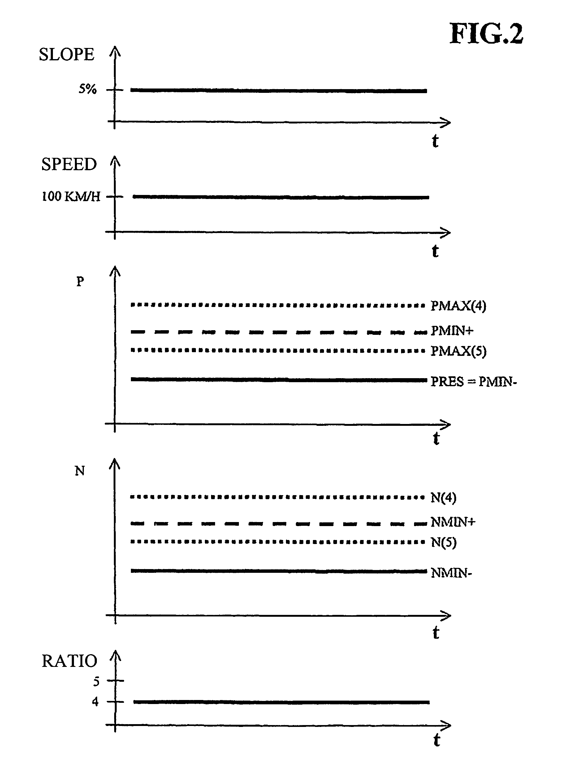
[0020]The method according to the invention ensures that the power that can be delivered by the motive power group at the current ratio is always higher than a threshold representative of the resisting load plus a margin, which makes it possible to ensure that a speed setpoint is maintained. This principle could be sufficient to eliminate the hunting problem that develops when the power available at the current ratio is insufficient to compensate for the resisting load. However, if the first and second thresholds were identical, oscillating ratio shifts could occur due to small fluctuations of the resisting load. This problem can be overcome by the functional hysteresis introduced by establishing different first and second thresholds.
[0022]In addition, the method according to the invention makes it possible to anticipate the downshift sufficiently when the resisting load increases, since, as soon as the power that can be delivered by the motive power group falls to a value below the thrust that must be delivered to maintain a speed setpoint plus a margin, the said downshift is demanded. Thus the downshift is produced in a manner sufficiently anticipated to prevent any speed fluctuation due to an increase of the resisting load, and so the method according to the invention is particularly well adapted to the use of a speed governor.
[0024]According to a first alternative version of the invention, the said powers that can be delivered by the motive power group at the current speed N(r) and at the speed N(r+) are the maximum powers that can be delivered by the motive power group at the speeds under consideration. As explained hereinafter, this alternative version makes it possible to simplify the estimate of the power that can be delivered by the motive power group at speeds N(r) and N(r+). In fact, a calculation of the power that can be delivered immediately by the motive power group at a ratio higher than the current ratio requires that the state of the engine power control at the instant of the shift of ratio be taken into account. In fact, at given engine speed, the driving power depends, for example, on the degree of opening of the intake butterfly valve (case of controlled-ignition engines) or on the fuel-injection conditions (case of diesel engines). However, it is not indispensable for proper functioning of the method to determine the immediate availability of the motive power group; instead, it can be replaced without problem by the value of the maximum power that can be delivered rapidly by the motive power group by means of an adjustment of the engine power control. This maximum power can be determined extremely simply from the single datum of an engine speed, for example by using a modeling of the characteristic curve of the motive power group to establish a correspondence between engine speed and maximum power.
[0033]Relationship R2 also shows that any error in estimation of the product of mass MV times acceleration γ or of the value of the braking force Ffreins directly affects the calculation of the resisting load. This is why the mass (MV) of the vehicle is advantageously determined by a dynamic estimate of the mass of the vehicle (as is described, for example, in the comments hereinafter relating to FIG. 1). Similarly, during braking phases, the calculation of the resisting load will advantageously include a step in which the value of the power produced by the brake system is determined, the said value being obtained from an information stream representative of the brake pressure and a model establishing a correspondence between the said pressure and the said braking power. In fact, such a method of determining the braking power makes it possible to obtain precise and reliable results. If necessary, it would be possible to estimate the braking force more roughly (for example, by assuming the force to be constant during braking actions).
[0035]It is useful to provide means for dynamically optimizing the functioning of the method according to the invention, for example by adjusting the value of margins ΔP+ and ΔP−. This is why it will be advantageously possible to determine margins ΔP+ and ΔP− by taking into account the current gear reduction ratio (r) of the transmission and / or a variable representative of the resisting load. However, to simplify implementation of the method according to the invention and to avoid the need to adjust two parameters, it will be possible to assign margin ΔP− a fixed value of zero and to choose a constant and strictly positive value for margin ΔP+.

Problems solved by technology

These algorithms lead to forced initiation of a downshift (shift to a lower ratio) upon detection of a loss of vehicle speed compared with a given setpoint.
The solutions for eliminating the hunting problem, as proposed in the aforesaid documents, are limited to the context of use of a speed-governing system, and they are not capable of anticipating sufficiently to avoid speed fluctuations during an increase of the resisting load exerted on the vehicle, downshifting being initiated only after detection of a substantial speed loss.
In addition, the case of use of a speed limiter poses a new problem compared with the prior art cited in the foregoing, in the sense that a speed limiter tends to function in a more extensive range of speed and ratios (approaching low speeds and low ratios) than does the speed governor, used mainly on the highway at high speed and at the highest transmission ratios.
U.S. Pat. Nos. 4,709,595 and 5,012,419 propose contrivances to attenuate the jolt associated with downshifting, but do not offer a solution to the need to anticipate the downshift.
These latter three documents certainly teach us elaborate methods for estimating the available acceleration at the higher ratio with good precision, but their teachings are limited to a strategy of inhibiting the shift to the higher ratio to eliminate the hunting problem, without giving any indication with regard to initiating the downshift.

Method used


Image

  • Method for controlling selection of an automatic transmission gear ratio
  • Method for controlling selection of an automatic transmission gear ratio
  • Method for controlling selection of an automatic transmission gear ratio

Examples


Embodiment Construction

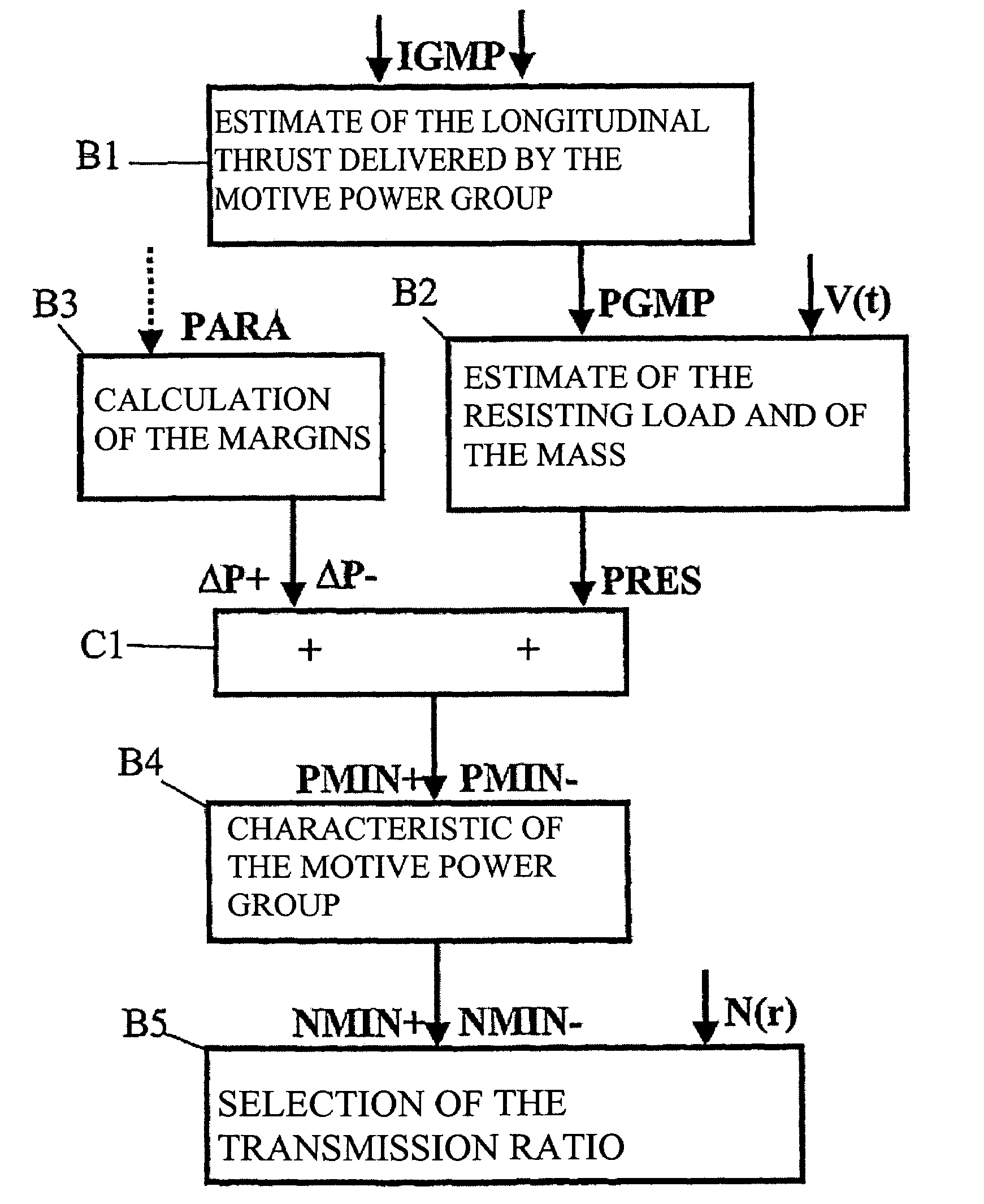
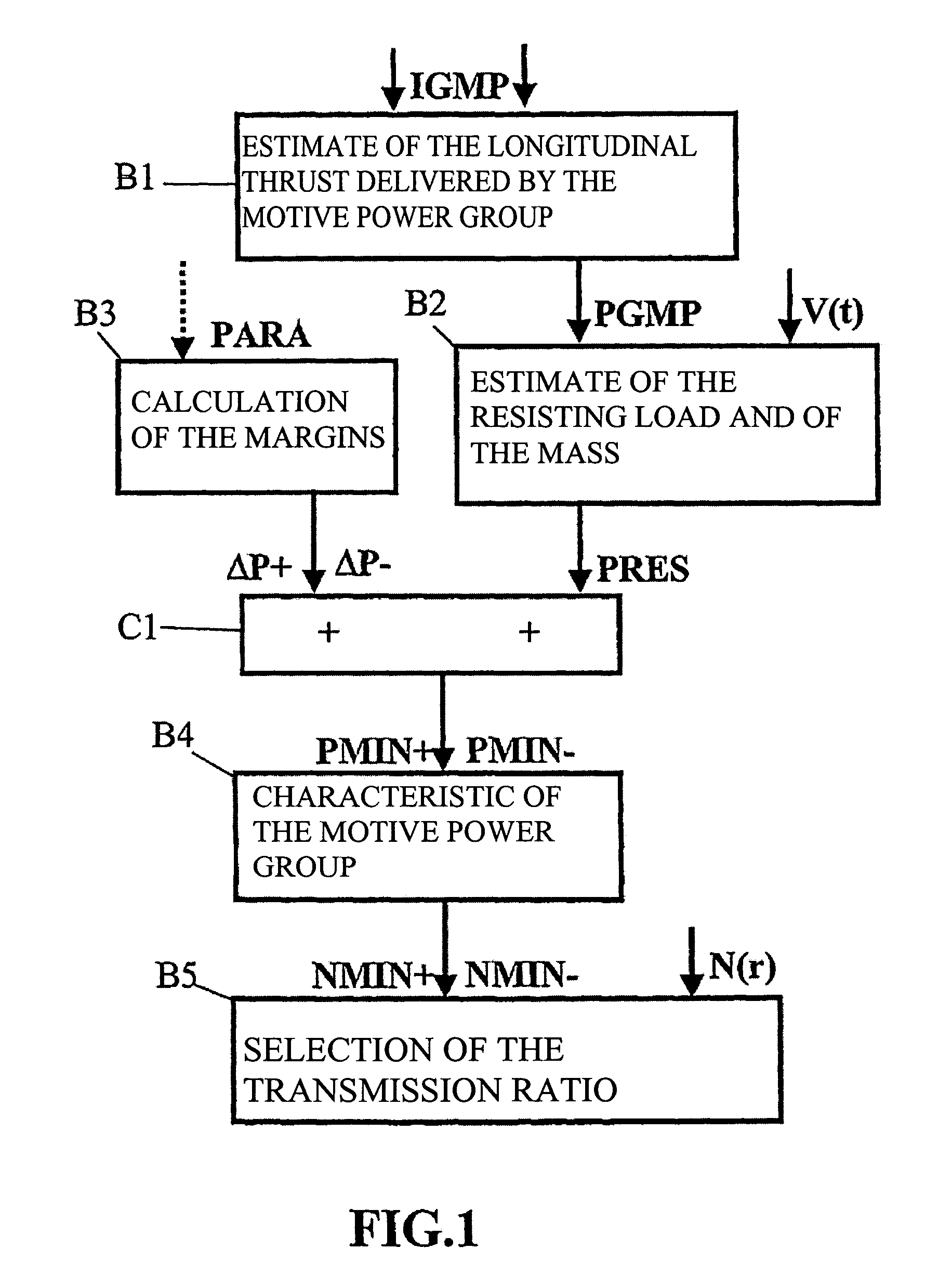
[0043]In FIG. 1, the steps of the method according to the invention are represented in the form of functional blocks B1, B2, B3, C1, B4, B5, which are interconnected by arrows representing transfers of variables. The transfers of variables not originating from processing by one of the functional blocks but originating, for example, from sensors situated on the motive power group or from engine-control components are indicated by arrows whose beginning is not connected to any functional block.

[0044]The current control systems of both gasoline and diesel engines are capable of estimating the effective torque delivered by the engine by means of available sensors (speed, pressures, temperatures, air flow, etc.) and of actuator-control variables (injection time, turbo pilot control, variable intake or distribution).

[0045]Knowing the state of the transmission (gear reduction ratio) and of the coupling component (coupler, clutch or torque converter), it is possible, from the datum of the e...


PUM


Abstract

A method for controlling selection of an automatic transmission gear ratio with staged ratios or constant variation for a vehicle including a control for preventing / allowing extension of the gear ratio or for controlling a shortening the transmission gear ratio if, at a current engine speed, the power is insufficient for maintaining the vehicle speed. The method prevents extension of the transmission gear ratio if the power available after the extension is insufficient for maintaining the vehicle speed; otherwise allowing extension of the transmission gear ratio.

Description

BACKGROUND OF THE INVENTION[0001]The present invention relates to a method for controlling the selection of the gear reduction ratio of a transmission for a vehicle equipped with a stepped-ratio or continuously variable automatic transmission, especially for operation of the said vehicle with a speed governor or limiter. It is known that specific strategies can be used to control the selection of the transmission ratio of a stepped-ratio automatic transmission in order to suppress the instabilities of automatic gearboxes known as the hunting phenomenon. This phenomenon is manifested by an excessive frequency of ratio changes from one ratio to a higher ratio and vice versa, when the resisting load exerted on the vehicle becomes large (inclined roadway, strong wind, etc.). In fact, when the resisting load increases, as in the case when the vehicle encounters an uphill stretch, the said vehicle tends to slow down, and the operator presses on the accelerator pedal in order to compensate...

Claims


Application Information

Patent Timeline
IPC IPC(8): G06F17/00B60K31/00B60T8/32F16H59/66F16H61/02F16H61/66
CPCF16H61/0213B60W2530/16Y10T477/6223F16H61/66F16H2061/161F16H2059/743Y10S903/917Y10S903/919Y10S903/918F16H2059/366F16H2061/0216Y10T477/6422Y10T477/623Y10T477/60Y10T477/6437Y10T477/6414Y10T477/636Y10T477/6424Y10T477/6388Y10T477/641F16H59/66F16H61/02
Inventor AUBERT, OLIVIER
Owner RENAULT SA
Learn More