
Lamination cooling system formation method

a technology of lamination cooling and formation method, which is applied in the direction of magnetic bodies, magnetic circuit shapes/forms/construction, manufacturing tools, etc., can solve the problems of increasing increasing the thermal impedance between, and reducing the continuous power rating of the motor, so as to reduce the cost of manufacturing a liquid cooled housing. , the effect of reducing the cost of manufacturing

Inactive Publication Date: 2009-05-12
AEROVIRONMENT INC
View PDF9 Cites 13 Cited by
  • Summary
  • Abstract
  • Description
  • Claims
  • Application Information

AI Technical Summary

Benefits of technology

[0009]In various embodiments, the present invention mitigates some or all of the needs mentioned above, providing cooling apparatus scheme for use with electric motors, or similar devices such as transformers, inductors, generators and the like. This cooling apparatus typically mitigates the above-described problems while offering improved heat transfer efficiency, reduced overall apparatus size, and / or reduced apparatus mass.
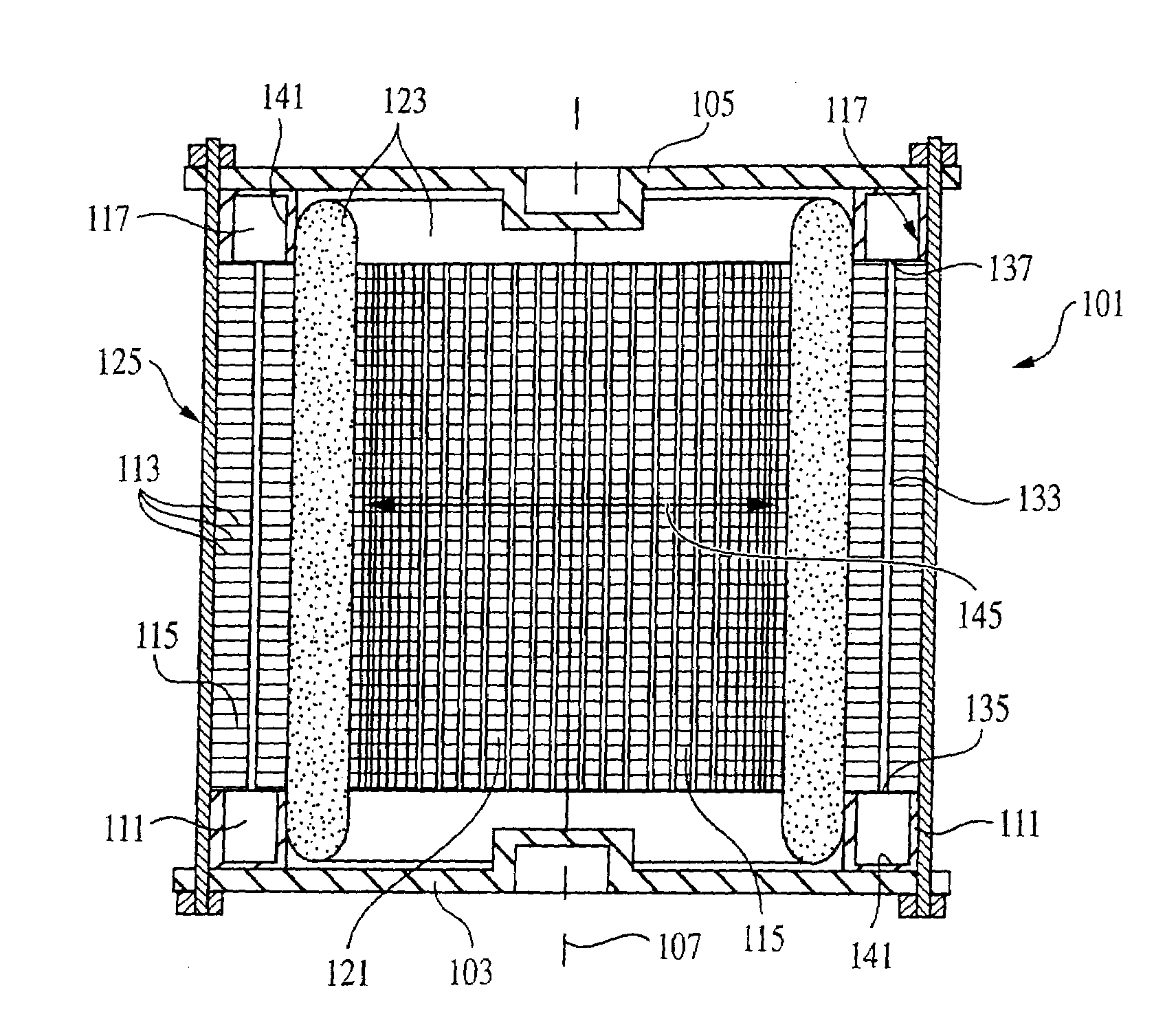
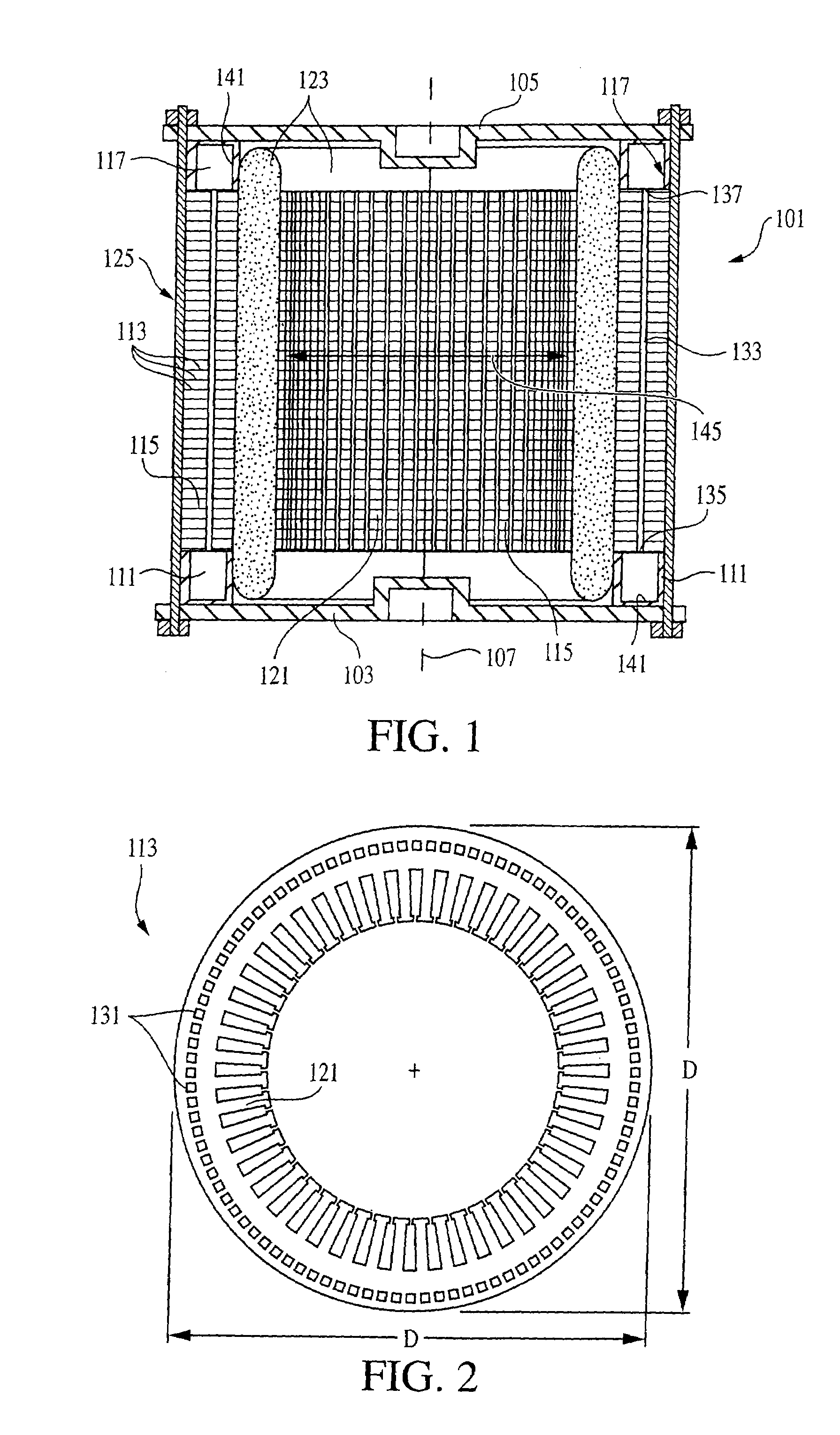
[0011]A feature of the invention is that gaps between the adjacent laminations are sealed to prevent a liquid cooling fluid in the passageways from exiting the lamination stack between adjacent laminations. This feature will generally provide for both the heat capacity advantages of a liquid cooling system and the structural advantages of the direct stator cooling that can be found in some air-cooled systems. Furthermore, these advantages are available without the large weight and container requirements of systems having an entire stator maintained in a coolant bath. In short, this feature provides for efficient cooling, with efficient size, weight and cost requirements.
[0012]In another feature of the invention, the seal between the laminations is preferably formed by applying sealant to the surfaces of the cooling-fluid passageways. The sealant is preferably of a material that can be solidified to nonporously coat the passageways, and of a type that will not be degraded by the cooling fluid. The sealant is preferably applied by flooding the passageways, preferably with the sealant under adequate hydrostatic pressure to inject the sealant into any voids between the laminations that could allow coolant to leak from the passageways and / or out of the lamination stack. The flooded sealant is then substantially drained (i.e., drained except for the portion of the sealant that entered voids and / or stuck to the passageway walls as a coating), and the removal of the excess (i.e., removable) sealant is aided by passing air through the passageways. Air pressure can be used to force the sealant into the voids, either in addition to or as an alternative to using hydrostatic pressure. Finally, the sealant is preferably cured by subjecting it to an appropriate temperature cycle. Advantageously, this feature generally provides not only for the advantages described above for the first feature, but also for the prevention of corrosion caused by the cooling fluid.
[0013]Another feature of some embodiments of the invention is that passageways can be designed to increase and decrease in size, and to curve, turn, subdivide, and even loop back, so as to offer control over the extent and location of the cooling. This feature can advantageously provide for control over stresses and degradation related to high temperatures and / or high temperature gradients, as well as provide for cooling of lamination locations that are not axially accessible through a lamination stack.
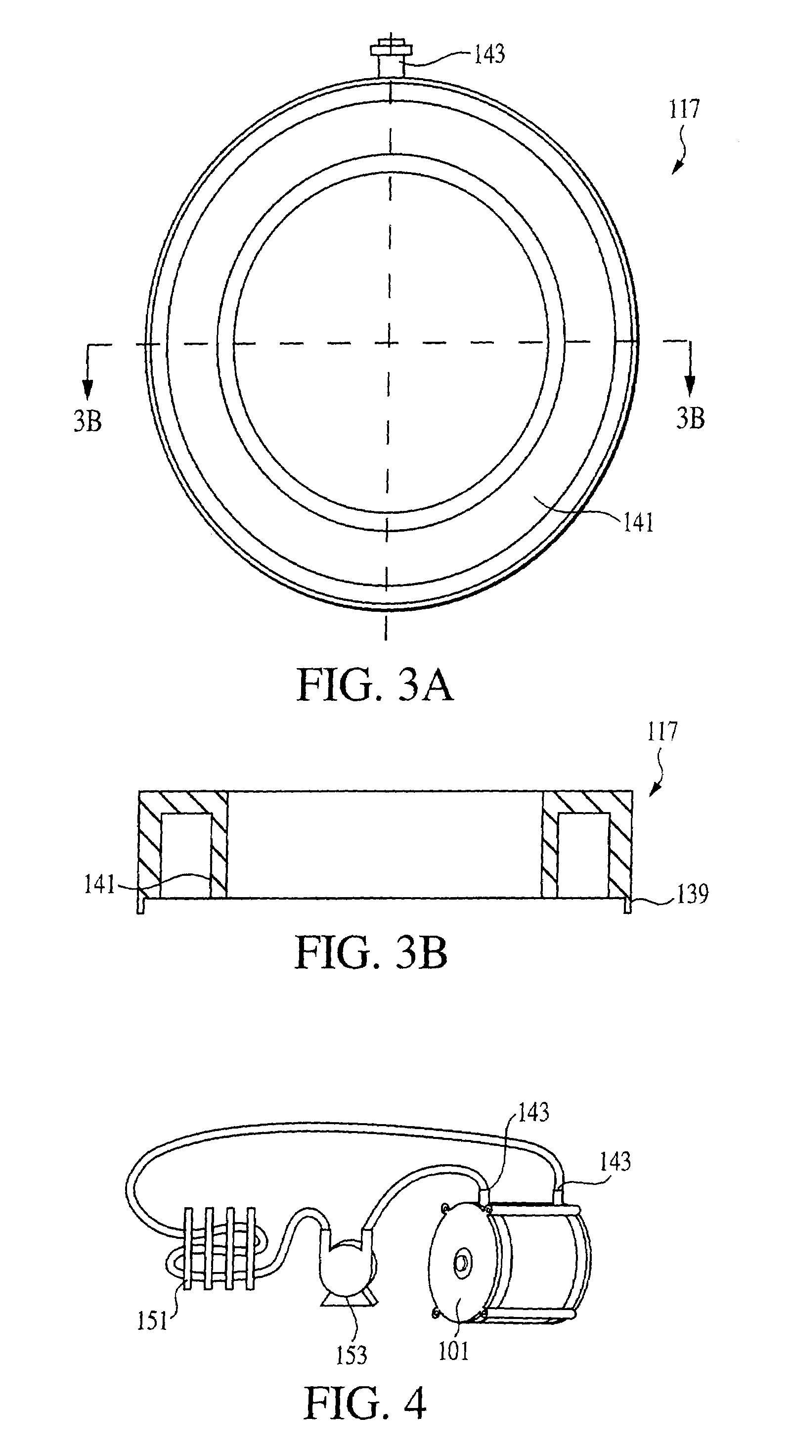
[0014]Yet another feature of some embodiments of the invention is that cooling-fluid manifolds can be used both to control fluid flow between input / output sources and various passageways, and to structurally support the lamination stack. This feature can advantageously provide for the use of cooling-fluid serially flowing through a plurality of passageways to provide bidirectional flow, potentially allowing for better temperature gradient control and larger passageway dimensions (and accordingly reduced material weight and manufacturing cost). This feature also allows for the lamination stack to be supported within a framework of tie rods and end bells that both support rotor bearings and support the manifolds. Furthermore, when combined with the second recited feature above, the cooling-fluid-containing interior of the manifolds can also be sealed and coated with sealant for the prevention of leaks and corrosion.

Problems solved by technology

Each of these aspects adds to the expense of manufacturing a liquid cooled housing.
A liquid-cooled housing will typically have small gaps between the stator and housing, causing increased thermal impedance between them, thereby reducing the continuous power rating of the motor.
Furthermore, the housing add size and weight to the stator and rotor.

Method used


Image

  • Lamination cooling system formation method
  • Lamination cooling system formation method
  • Lamination cooling system formation method

Examples


first embodiment

[0058]With reference to FIGS. 5A-5C, a first variation of stator housing of the type described in the first embodiment can be configured for bidirectional flow. Rather than using first and second manifold members each having a cooling-fluid port and a single circumferential manifold cavity, the manifold members are configured to direct cooling fluid bidirectionally through a lamination stack 215. More particularly a first manifold member 211 is configured with a first cooling-fluid port 261, a second cooling-fluid port 263, a first semi-circumferential manifold cavity 265 and a second semi-circumferential manifold cavity 267. The first cooling-fluid port 261 is in direct fluid communication with the first semi-circumferential manifold cavity 265, and the second cooling-fluid port 263 is in direct fluid communication with the second semi-circumferential cavity 267. A second manifold member 217 is configured with a single circumferential manifold cavity 271, and no cooling-fluid port....

second embodiment

[0081]Manifold member designs for the second embodiment resemble those of the motor embodiment described above, but are rectangular rather than round. Similar to the various embodiment variations of the motor, each manifold member 505, 507 of the inductor / transformer embodiment includes one or more cooling-fluid ports 519, and forms one or more cavities that are used as manifolds to distribute and / or receive cooling fluid to / from the passageways 517 within the core structure 501. As with the manifold members for the motor application, sealing between the manifold members and the lamination stack faces can be achieved by either conventional gasket techniques or by conventional O-ring techniques.

[0082]Because it is desirable to have cooling provided to the center prong 509 of the E-shaped element, and because the windings 503 prevent direct access between the manifold members 505, 507 and center-prong passages 521 that pass through the center prong, the core 501 includes nonlinear, mu...


PUM


Abstract

An electric motor, transformer or inductor having a cooling system. A stack of laminations have apertures at least partially coincident with apertures of adjacent laminations. The apertures define straight or angled cooling-fluid passageways through the lamination stack. Gaps between the adjacent laminations are sealed by injecting a heat-cured sealant into the passageways, expelling excess sealant, and heat-curing the lamination stack. Manifold members adjoin opposite ends of the lamination stack, and each is configured with one or more cavities to act as a manifold to adjacent passageway ends. Complex manifold arrangements can create bidirectional flow in a variety of patterns.

Description

[0001]The present application is a divisional application of application Ser. No. 10 / 431,324, filed May 6, 2003 now U.S. Pat. No. 6,954,010, which claims priority from Provisional Application Ser. No. 60 / 378,276, filed May 6, 2002, both of which are incorporated herein by reference for all purposes.[0002]This invention was made with Government support under grant DE-FG03-00ER829-40 awarded by the Department of Energy. The Government has certain rights in this invention.BACKGROUND[0003]This invention relates generally to methods and apparatus for cooling lamination stacks, and, more particularly, to apparatus and methods for cooling electric motors for use in electric and hybrid vehicles.[0004]Present day electric and hybrid vehicles typically use inverter-driven, radial gap motors that are either AC induction or DC brushless type motors. Both of these motor types are similar in that an interior rotor rotates within an exterior stator. The stator can be made of a lamination stack (i....

Claims


Application Information

Patent Timeline
Patent Type & Authority Patents(United States)
IPC IPC(8): H02K15/00H02K15/14H02K15/16H02K1/20
CPCH02K1/20Y10T29/49297Y10T29/49455Y10T29/49009Y10T29/49719Y10T29/49078
Inventor RIPPEL, WALLY E.KOBAYASHI, DARYL M.
Owner AEROVIRONMENT INC
Learn More