Rearview mirror assembly encompassing a radar detector and/or laser detector

a technology of laser detectors and rearview mirrors, applied in the direction of machine supports, instruments, other domestic objects, etc., can solve the problems of reducing the ability of the windshield to adhere securely, and affecting the use of radar detectors

Inactive Publication Date: 2009-05-12
BANKO INDS
View PDF9 Cites 48 Cited by
  • Summary
  • Abstract
  • Description
  • Claims
  • Application Information

AI Technical Summary

Problems solved by technology

There are several factors that make the use of radar detectors unpleasant for the consumer and prevent its more widespread use.
Using suction cups presents difficulty because the suction cups can become loose and have to be readjusted.
They also rely on the windshield being clean and dry however, dirt and oils are introduced each time the mount is reattached, further reducing its ability to adhere securely to the windshield.
Loose suction cups can lead to driver distraction and pose a safety hazard when the device falls off of the windshield while the vehicle is traveling.
As most vehicles only have one such outlet, using it for a radar detector prevents it from being used for powering additional devices such as a mobile phone, portable music player, etc.
Mounting a radar detector to the windshield with a cable dangling can be distracting to the driver and can obstruct his or her view of the road ahead.
This cable also inhibits the use of other controls on the vehicle console such as thermostat, audio, and navigation controls.
Windshield mounts also make the radar detector visible from outside the vehicle, encouraging break-in and theft.
In the case of older vehicles, specifically the American muscle cars of the 1960s and 1970s, the suction cups are an inadequate mount because of the steep angle at which windshields on those vehicles are mounted.
While this is suitable for the majority of vehicles, in a muscle car this mounts the radar detector at an angle such that the radar detector receiver will be pointed downward and not allow for maximum sensitivity of the device.
Depending on the geometry of the radar detector enclosure, many angularly adjustable mounts are not able to support the load of the device because it creates a great moment arm about the mounted suction cups, causing the radar detector to be unstable and fall off the windshield.
This can be especially distracting and potentially hazardous to the driver and passengers of the vehicle.
The second mounting mentioned, including a sun visor clip, prohibits the use of the sun visor for its original intention, thus creating a safety hazard in bright sunlight.
The sun visor clip method also frequently has inadequate connection between the clip and the device, causing the device to fall off of the sun visor and into the face or lap of the driver, creating an additional safety hazard.
In the aforementioned case of a muscle car, the sun visor mounting clips frequently cause two problems.
First, these clips are designed to accommodate the modern sun visor that is much thicker than older models and the clip does not attach securely to the sun visor of a muscle car.
In most cases, the hinge on the sun visor of a muscle car cannot support the additional load of the radar detector's weight.
The design of U.S. Pat. No. 5,667,176 to Zamarripa (1997) fails to account for the awkward and potentially hazardous power cable or the security risks with a device that is visible from outside the vehicle.
Thus, the problems of the obtrusive cable dangling down to a cigarette-lighter power outlet still remain.
U.S. Pat. No. 4,630,904 to Pastore (1986) discloses a rearview mirror assembly comprising of a two-way mirror with information display designed to maximize reflective surface when information is not displayed; however, a two-way mirror does not provide optimal image reflectance, reducing the effectiveness of the rearview mirror assembly's primary function.
More specifically, because both sides of the two-way mirror have variable lighting conditions for instance, daytime versus nighttime on the exposed side and Light Emitting Diode (LED) illumination versus non-illumination on the interior, the reflectance of the mirror varies greatly and cannot be relied upon for the primary function.
The biggest limitation of this design is that the transparency is only sensitive to wavelengths of light and not radar waves, preventing the device from detecting radar signals.

Method used


Image

  • Rearview mirror assembly encompassing a radar detector and/or laser detector
  • Rearview mirror assembly encompassing a radar detector and/or laser detector
  • Rearview mirror assembly encompassing a radar detector and/or laser detector

Examples


first embodiment

b>4 and 11-12

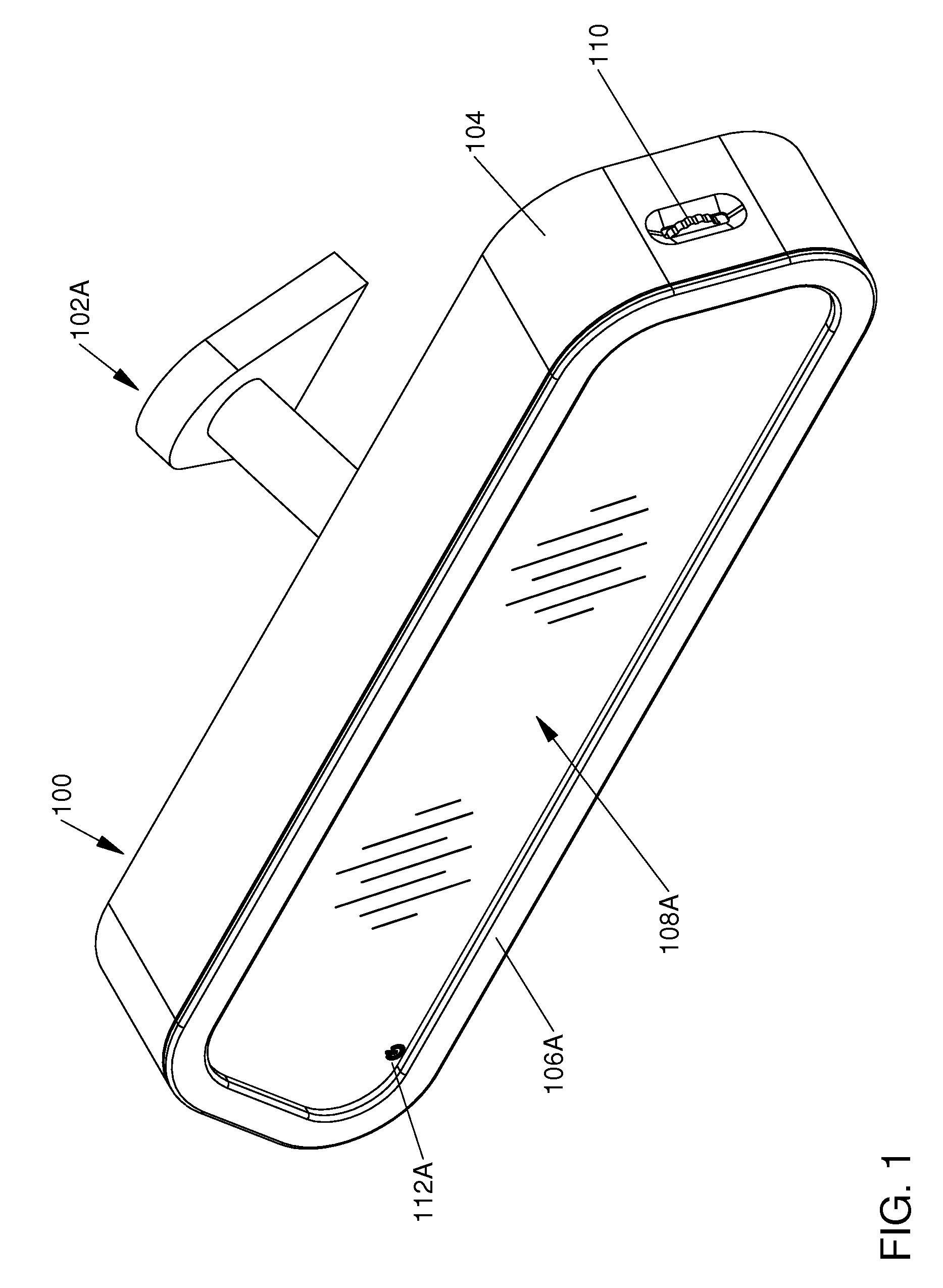
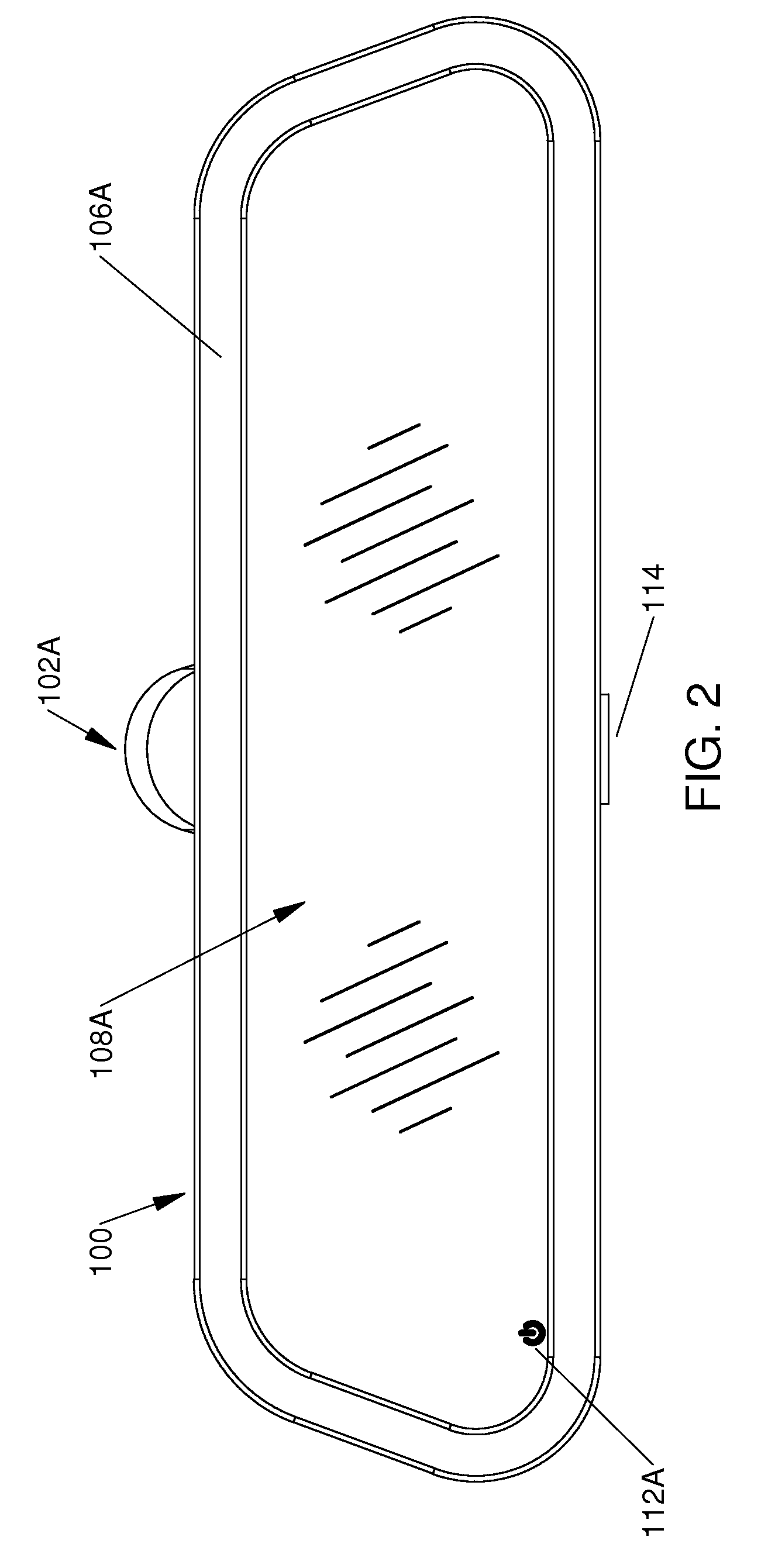
[0040]One embodiment of the rearview mirror assembly is illustrated in FIG. 1 (front perspective view), FIG. 2 (front view in standby mode), FIG. 3 (front view with illuminated indicators), and FIG. 4 (rear view).

[0041]FIG. 1 shows a front perspective view of rearview mirror assembly 100, and windshield mount assembly 102A that enables rearview mirror assembly 100 to attach to a vehicle windshield. The mirror assembly 100 consists of a housing 104 and a bezel 106A, which supports mirror glass assembly 108A. Mirror assembly 100 accommodates multi-function roller / push button 110 and multi-function push button 114 (shown in FIG. 2). Internal to mirror assembly 100 is a PCB assembly 136 which contains controlling electronics for the detection and notification of radar and laser signals. Functions provided by the PCB assembly 136 include but are not limited to illumination of indicators via LEDs, audible notification via speaker, user inputs. Multi-function roller / push butto...

second embodiment

FIGS. 5-6—Second Embodiment

[0050]The second embodiment is differentiated by the masked perimeter of the mirror glass assembly 108A.

[0051]FIG. 5 consists of rear view mirror assembly 100 in standby mode and shows the presence of windshield mount assembly 102A, bezel 106A, multi-function push button 114, and mirror glass assembly 108A. Power indicator 112B is illuminated to indicate power to the device and standby mode.

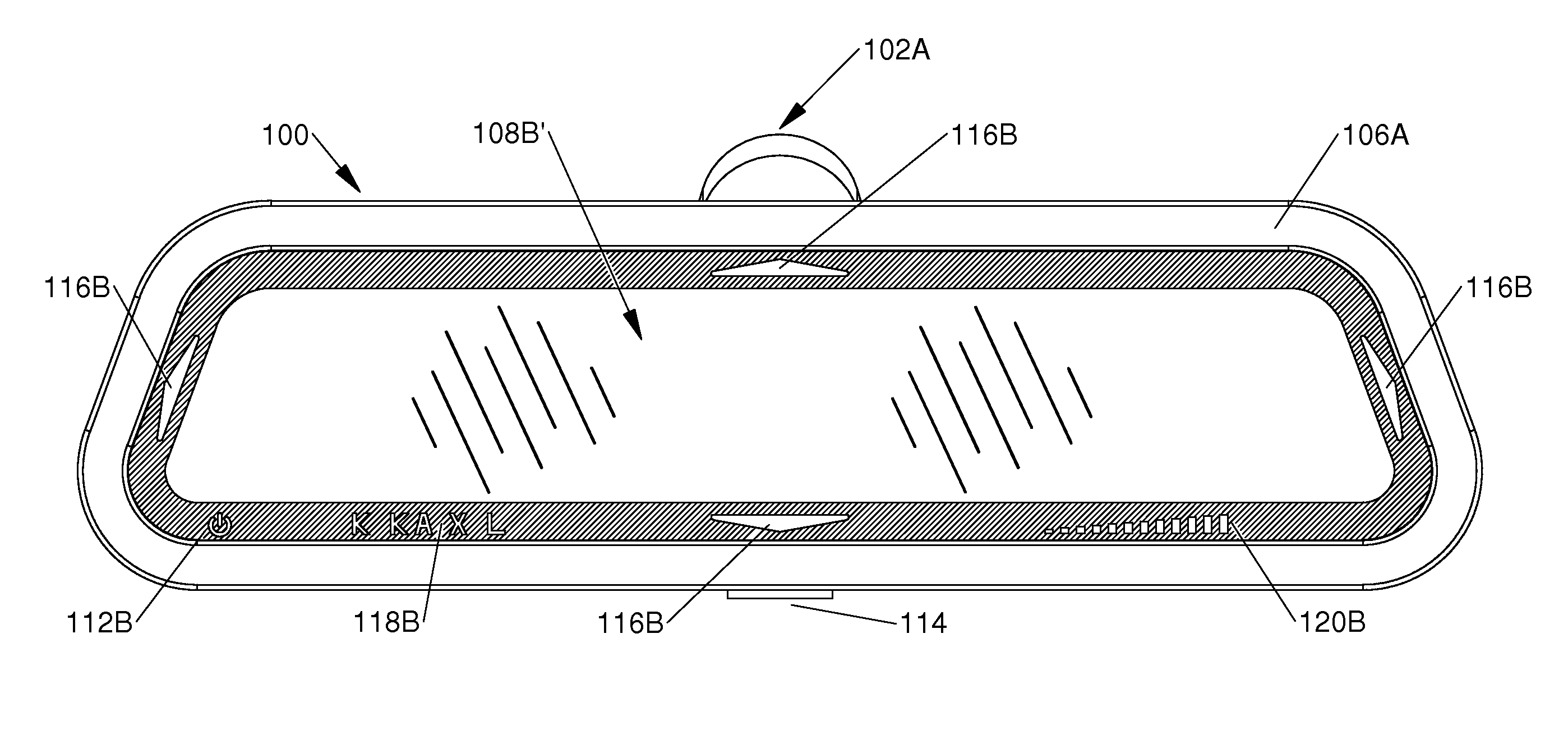
[0052]FIG. 6 consists of rear view mirror assembly 100 with all available indicators illuminated. One example when this occurs is during the startup sequence after the device has been powered. Also shown are windshield mount assembly 102A, bezel 106A, multi-function push button 114, and mirror glass assembly 108B′. Illuminated indicators include power indicator 112B, directional indicators 116B, signal type indicator 118B, and intensity indicator 120B are visible in mirror glass assembly 108B′.

third embodiment

FIGS. 7-8—Third Embodiment

[0053]The third embodiment is differentiated by the etched indicators of the mirror glass assembly 108C.

[0054]FIG. 7 consists of rear view mirror assembly 100 when in standby mode. Also shown are windshield mount assembly 102A, bezel 106A, multi-function push button 114, and mirror glass assembly 108C. Power indicator 112C is illuminated indicating power to the device and standby mode. Directional indicators 116C, signal type indicator 118C, and intensity indicator 120C are visible in mirror glass assembly 108C but are not illuminated.

[0055]FIG. 8 consists of rear view mirror assembly 100 with all available indicators illuminated. One example when this occurs is during the startup sequence after the device has been powered. Also shown are windshield mount assembly 102A, bezel 106A, multi-function push button 114, and mirror glass assembly 108C′. Illuminated indicators include power indicator 112C, directional indicators 116C′, signal type indicator 118C′, a...


PUM


Abstract

One embodiment of a rearview mirror encompassing a plurality of radar detectors and laser detectors comprises of an opaque housing, a rearview mirror assembly, a universal mount, and a PCB assembly providing all of the illumination, audible indication, logic, user inputs, and radar and laser detection. Visual indications of radar or laser signals via illuminated indicators visible through the mirror, provide a fully functioning rearview mirror, when in standby mode. The device accommodates a plurality of mounts in order to accommodate all vehicle types. The geometry and mounting locations provide for more sensitive and accurate detection of radar and laser signals, while neither distracting the drive, detracting from the aesthetic nature of the vehicle, or causing a safety hazard.

Description

CROSS-REFERENCE TO RELATED APPLICATIONS[0001]Not ApplicableFEDERALLY SPONSORED RESEARCH[0002]Not ApplicableSEQUENCE LISTING OR PROGRAM[0003]Not ApplicableBACKGROUND[0004]1. Field of Invention[0005]This invention generally relates to a rearview mirror assembly, specifically to a rearview mirror assembly for use in vehicles and incorporating functions of a radar detector and / or laser detector.[0006]2. Prior Art[0007]Radar detectors for vehicles have been in common use for many years as they provide a desired function for the vehicle driving public. There are several factors that make the use of radar detectors unpleasant for the consumer and prevent its more widespread use.[0008]Radar detectors are typically after-market purchases and are installed as home using a variety of simple included mounts. When using these included mounts, consumers are given instructions as to where to mount the device in order to experience the greatest performance from the device. An ideal position is in t...

Claims


Application Information

Patent Timeline
Patent Type & Authority Patents(United States)
IPC IPC(8): G01S7/42B60R1/12
CPCB60R1/12G01S7/022G01S7/4806B60R2001/1215B60R2001/1223B60R2001/1276
Inventor BANKO, SARAH V.BANKO, JOSHUA D.
Owner BANKO INDS
Why Eureka
Try Eureka