Semiconductor device and impedance adjusting method thereof
a technology of impedance adjustment and semiconductor, applied in the direction of pulse technique, digital storage, reliability increasing modifications, etc., can solve the problems of lower-speed impedance adjusting operation and increase the area occupied by the circuit for adjusting, and achieve the effect of reducing the area of the impedance adjusting circuit and higher-speed impedance adjusting
- Summary
- Abstract
- Description
- Claims
- Application Information
AI Technical Summary
Benefits of technology
Problems solved by technology
Method used
Image
Examples
embodiment 1
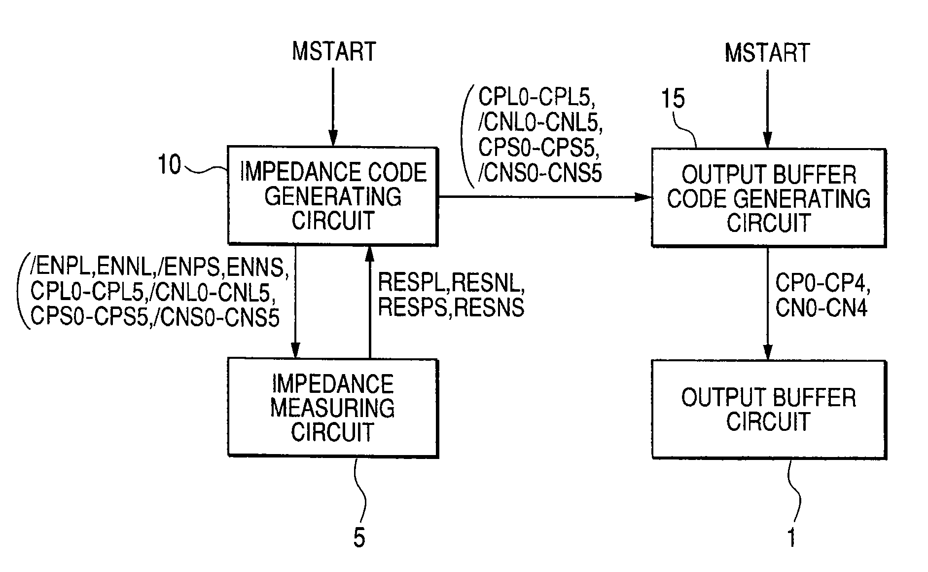
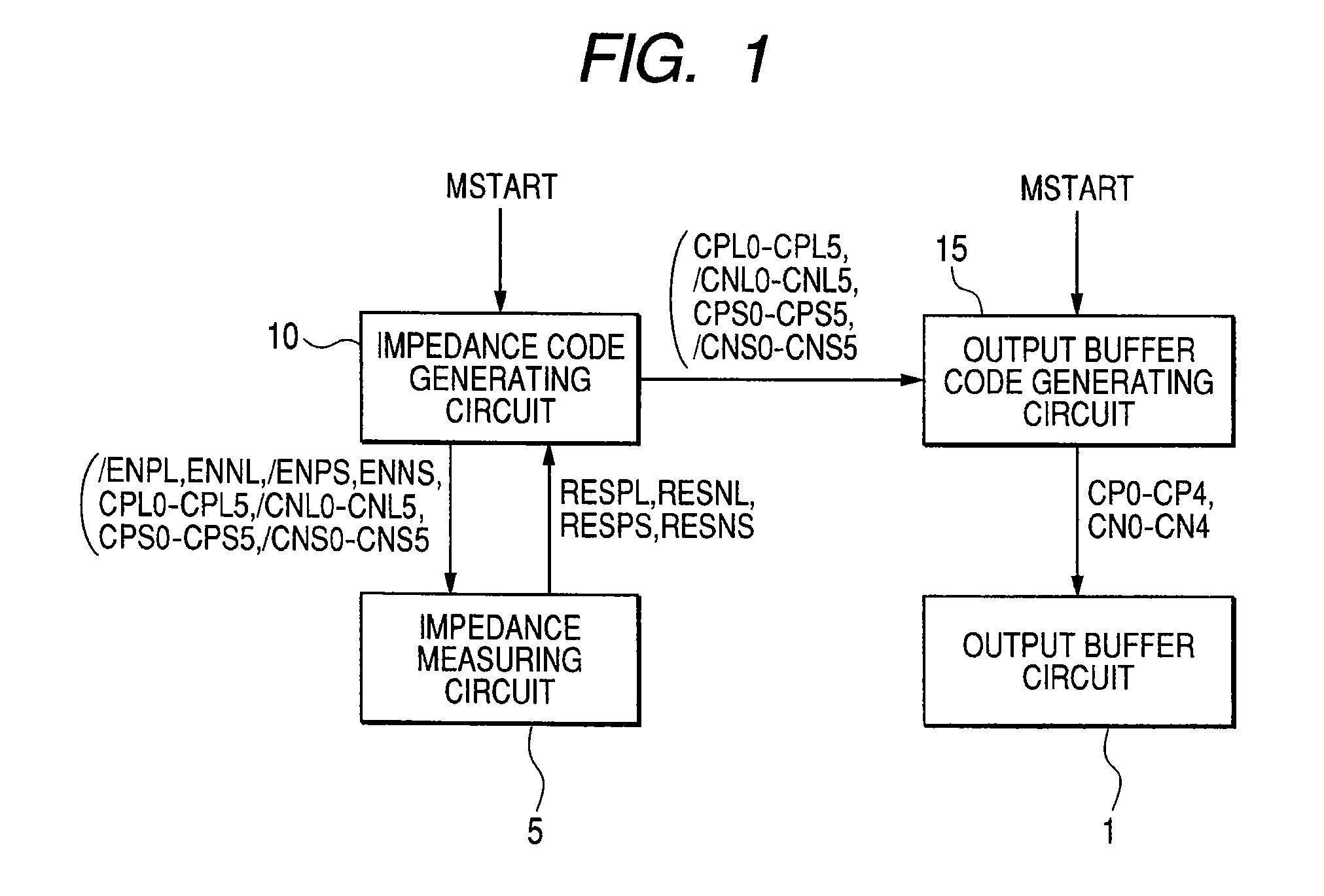
[0039]FIG. 1 is a schematic block diagram of a semiconductor device comprising an output buffer circuit 1 capable of impedance adjustment according to the first embodiment of the present invention.
[0040]Referring to FIG. 1, the semiconductor device according to the first embodiment comprises the output buffer circuit 1, an impedance measuring circuit 5 as an impedance adjusting circuit for adjusting an impedance, an impedance code generating circuit 10 for generating impedance codes based on the result of measurement from the impedance measuring circuit 5, and an output buffer code generating circuit 15 for generating output buffer codes for setting the impedance of the output buffer circuit 1 to a desired value based on the impedance codes from the impedance code generating circuit 10.
[0041]The impedance code generating circuit 10 outputs control signals / ENPL, ENNL, / ENPS, and ENNS to the impedance measuring circuit 5 in response to a control signal MSTART inputted thereto and gen...
embodiment 2
[0210]FIG. 10 is a schematic block diagram of a semiconductor device 1000 according to the second embodiment of the present invention.
[0211]A description will be given to the case where the semiconductor device 1000 according to the second embodiment is coupled to a memory DRAM (Dynamic Random Access Memory) 1001 and various control signals are outputted from a control circuit 20 included in the semiconductor device 1000 to the DRAM 1001.
[0212]Referring to FIG. 10, the semiconductor device 1000 according to the second embodiment comprises the control circuit 20 for outputting the various control signals to the DRAM 1001, output buffer circuits 1 and 1# for outputting the output signals from the control circuit 20 to the DRAM 1001, and impedance adjusting circuits provided in association with the output buffer circuits 1 and 1# to adjust the respective impedances of the output buffer circuits 1 and 1#. The impedance adjusting circuits for the output buffer circuits 1 and 1# include i...
embodiment 3
[0219]The second embodiment shown above has described the method in which the control signal MSTART is also outputted when the control unit 20 outputs the control signal AUTOREF as the auto-refresh command to the DRAM 1001 to simultaneously implement the generation of the impedance codes and the generation of the output buffer codes.
[0220]However, to implement impedance adjustment in the output buffer circuits 1 and 1#, it is necessary to perform impedance measurement, the generation of the impedance codes based on the impedance measurement, and the generation of the output buffer codes based on the impedance codes, as described above. Accordingly, a certain length of period is needed to implement impedance adjustment.
[0221]When consideration is given to the time required to perform impedance measurement, the generation of the impedance codes based on the impedance measurement, and the generation of the output buffer codes based on the impedance codes, there is the possibility that ...
PUM
 Abstract
Description
Claims
Application Information
 - R&D
- Intellectual Property
- Life Sciences
- Materials
- Tech Scout
- Unparalleled Data Quality
- Higher Quality Content
- 60% Fewer Hallucinations
Browse by: Latest US Patents, China's latest patents, Technical Efficacy Thesaurus, Application Domain, Technology Topic, Popular Technical Reports.
© 2025 PatSnap. All rights reserved.Legal|Privacy policy|Modern Slavery Act Transparency Statement|Sitemap|About US| Contact US: help@patsnap.com


