
Common path time domain optical coherence reflectometry/tomography device

a time domain, optical coherence reflectometer technology, applied in measurement devices, scientific instruments, instruments, etc., can solve the problems of domain reflectometry/tomography devices, secondary interferometers that must include, and faraday mirrors are known to be expensiv

Inactive Publication Date: 2009-05-26
IMALUX CORP
View PDF3 Cites 65 Cited by
  • Summary
  • Abstract
  • Description
  • Claims
  • Application Information

AI Technical Summary

Benefits of technology

[0012]In accordance with the present invention, there are provided common path time domain OCR / OCT devices that eliminate the necessity of using Faraday mirrors.
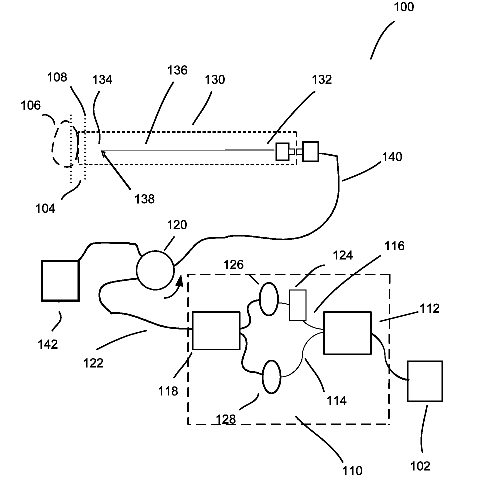
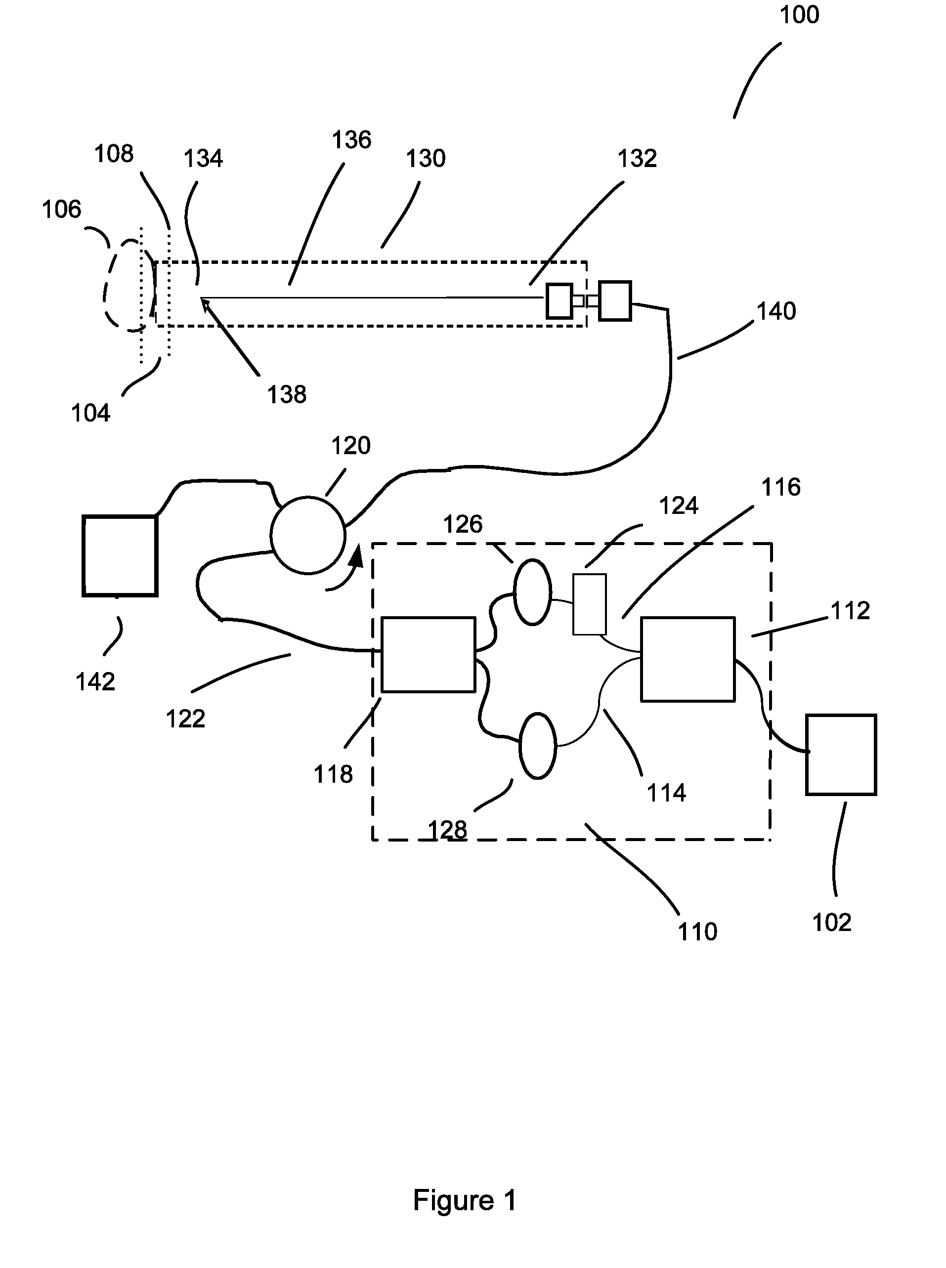
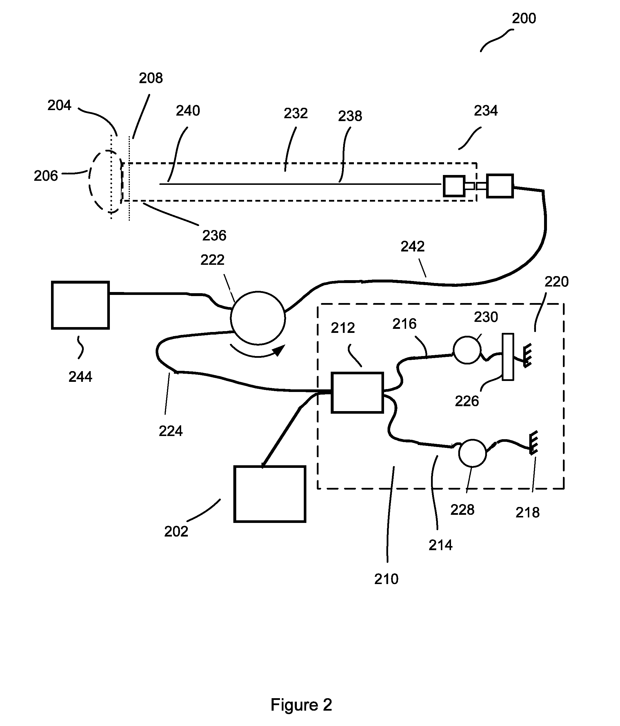
[0027]Thus, in accordance with the subject invention, unlike previously known common path time domain OCT / OCR devices, optical radiation from a source is first split into two replicas, which are then delivered to an associated sample by a delivering device, the delivering device being, preferably, an optical fiber probe. The tip of the optical fiber probe serves as a reference reflector and also serves as a combining element that produces a combination optical radiation by combining an optical radiation returning from the associated sample with a reference optical radiation reflected from the reference reflector. The topology of the devices of the subject invention eliminates the necessity of using Faraday mirrors, and also allows for registering a cross-polarized component of the optical radiation reflected or backscattered from the associated sample, as well as a parallel-polarized component.

Problems solved by technology

A limitation to previously known common path time domain reflectometry / tomography devices is that the secondary interferometer necessarily includes Faraday mirrors to compensate for static and dynamic polarization changes in the interferometer arms.
However, Faraday mirrors are known to be expensive, thus increasing the overall expenses for device manufacturing.
In addition, the performance of Faraday mirrors is wavelength and temperature dependant, leading to a requirement of changing the Faraday mirrors when switching to a different wavelength and / or including additional tuning and temperature stabilizing means.
Another limitation to previously known common path time domain reflectometry / tomography devices is that the registered interference signal is responsive only to the non-depolarized portion, or in other words, responsive only to the parallel-polarized component of the optical radiation reflected or backscattered from the sample.

Method used


Image

  • Common path time domain optical coherence reflectometry/tomography device
  • Common path time domain optical coherence reflectometry/tomography device
  • Common path time domain optical coherence reflectometry/tomography device

Examples


Embodiment Construction

[0034]The subject application is directed to systems and methods for visualizing subsurface regions of samples, and more specifically, to a time domain optical coherence reflectometer and time domain optical coherence tomography device that provide internal depth profiles and depth images of samples. Modifications of the common path time domain optical coherence reflectometer are illustrated by means of examples of optical fiber devices being part of an apparatus for optical coherence tomography, although it is evident that they may be implemented with the use of bulk optic elements, and may be used as independent devices. The optical fiber implementation is preferable for use in medical applications, especially in endoscopy, where flexibility of the optical fiber provides convenient access to different tissues and organs, including internal organs via an endoscope. However, the whole device, or any part of it, can be implemented using traditional bulk optics: mirrors, prisms etc.

[0...


PUM


Abstract

In common path time domain OCT / OCR devices optical radiation from a source is first split into two replicas, which are then delivered to an associated sample by an optical fiber probe. The tip of the optical fiber probe serves as a reference reflector and also serves as a combining element that produces a combination optical radiation by combining an optical radiation returning from the associated sample with a reference optical radiation reflected from the reference reflector. The topology of the devices eliminates the necessity of using Faraday mirrors, and also allows for registering a cross-polarized component of the optical radiation reflected or backscattered from the associated sample, as well as a parallel-polarized component.

Description

BACKGROUND OF THE INVENTION[0001]The present invention relates to systems and methods for visualizing subsurface regions of samples, and more specifically, to a time domain optical coherence reflectometer (OCR) and time domain optical coherence tomography (OCT) device that provide internal depth profiles and depth resolved images of samples.[0002]Optical coherence reflectometry / tomography involves splitting an optical radiation to at least two portions, and directing one portion of the optical radiation toward a subject of investigation. The subject of investigation will be further referred to as a “sample”, whereas the portion of optical radiation directed toward the sample will be further referred to as a “sample portion” of optical radiation. The sample portion of optical radiation is directed toward the sample by means of a delivering device, such as an optical probe. Another portion of the optical radiation, which will be further referred to as “reference portion”, is used to p...

Claims


Application Information

Patent Timeline
Patent Type & Authority Patents(United States)
IPC IPC(8): G01B9/02
CPCG01N21/4795G01B9/02057G01B9/02091G01B2290/70
Inventor FELDCHTEIN, FELIX I.
Owner IMALUX CORP
Learn More