Temporal interferometric signal modeling with constant phase shift in white light interferometry

a technology of interferometry and signal modeling, applied in the field of white light phase shifting interferometry, can solve the problems of inability to profile objects with uniform surfaces, non-linear phase of interferogram change, and loss of wlpsi's ability to profile such objects

Active Publication Date: 2009-05-26
KLA CORP
View PDF3 Cites 5 Cited by
  • Summary
  • Abstract
  • Description
  • Claims
  • Application Information

AI Technical Summary

Problems solved by technology

Although white light phase shifting interferometry (WLPSI) is capable of measuring surfaces with nanometer precision and with step height greater than one-fourth of a wavelength, the technique is only able to profile objects with uniform surface properties, and without transparent thin films.
Typically, WLPSI loses its ability to profile such objects.
However, the material properties of a PZT cause the phase of interferogram change to be non-linear with respect to the time during the acquisition.
Such non-linear phase shifts result in errors in sampling the temporal interferometric signal at each pixel of the interferograms.
Such sampling errors greatly deteriorate the measurement accuracy of the signal modeling technique.

Method used


Image

  • Temporal interferometric signal modeling with constant phase shift in white light interferometry
  • Temporal interferometric signal modeling with constant phase shift in white light interferometry
  • Temporal interferometric signal modeling with constant phase shift in white light interferometry

Examples


Embodiment Construction

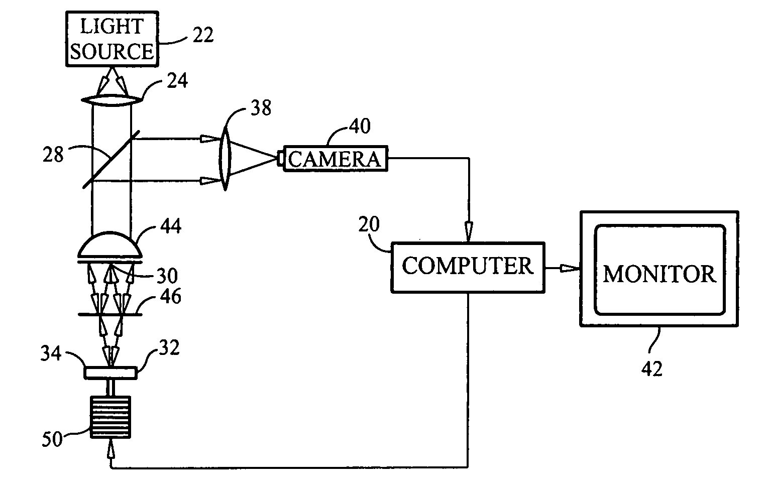
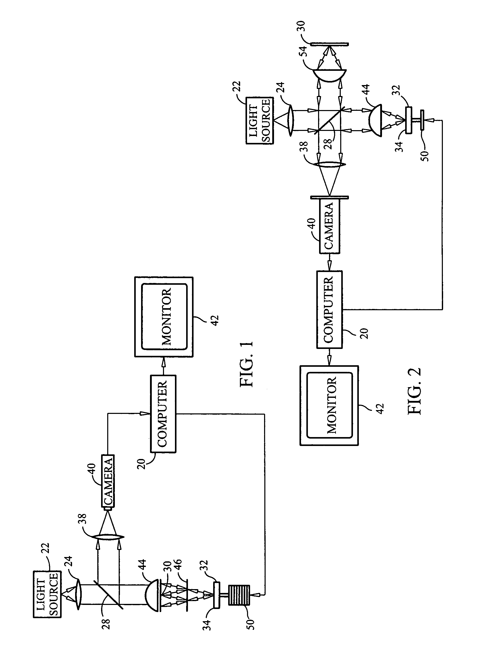
[0011]FIG. 1 is a schematic diagram of a Mirau interferometer system which may be used in conjunction with the practice of the method of the various embodiments of this invention. As shown in FIG. 1, the interferometer is controlled by a processor or computer 20 which coordinates the operation of a phase shifting driving mechanism 50 with other components of the system. The white light from the source 22 is supplied through a collimating lens 24 to a beam splitter 28 which supplies the collimated light to an objective lens 44. The lens 44 in turn supplies light to a reference flat in the form of a reference mirror 30, and to a further beam splitter 46 in accordance with the conventional operation of such an interferometer.

[0012]The reflected light beams from both the reference flat 30 and from both surfaces of a measurement object or test piece 32 are directed by the beam splitter 28 to an imaging lens 38, which supplies simultaneously multiple interferograms to a CCD camera 40, or ...


PUM


Abstract

A method for determining the surface topography of an object with various surface properties in white light interferometry first generates a set of interferograms, produced by a phase shift driving mechanism supplied with known inputs, obtained from a single reflective surface at the location of the test piece. The sequence of interferograms from the test piece then is used to calibrate a sequence of inputs to the phase shift driving mechanism to compensate for non-linear characteristics of the phase shifting mechanism. The temporal interferometric signal or its transform at each pixel of a set of subsequently acquired interferograms from a test piece then is compared with signals or their transforms modeled with different properties of the measuring surface. The measured surface properties which generate a best match to the modeling surface properties are selected as the desired signal.

Description

BACKGROUND[0001]This invention is related to the field of white light phase shifting interferometry. Phase-shifting interferometry (PSI) has proven to be a highly accurate and efficient method for the measurement of single reflective surfaces in a variety of applications including optical testing, surface profilometry, surface roughness estimation, and surface displacement measurement. PSI was first introduced by Bruning et al. in 1974, Digital Wavefront Measuring Interferometer for Testing Optical Surfaces and Lenses, Applied Optics 13, 2693-26703 (1974).[0002]The fundamental concept of PSI is that the phase of an interferogram can be extracted by acquiring a set of a few sequentially phase-shifted interferograms of the original interferogram with a constant phase shift between any two adjacent interferograms (or intensity frames). These phase shifted interferograms are produced by changing the optical path difference (OPD) between a measurement surface and a reference surface, or ...

Claims


Application Information

Patent Timeline
Patent Type & Authority Patents(United States)
IPC IPC(8): G01B11/02
CPCG01B9/02057G01B9/0209G01B9/02072
Inventor TANG, SHOUHONG
Owner KLA CORP
Why Eureka
Try Eureka