
Electromagnetically operated friction disk clutch and rotor for a clutch of this type

a technology of friction disk and rotor, which is applied in the direction of electrical apparatus, control systems, dynamo-electric machines, etc., can solve the problems of comparatively time-consuming and cost-intensive procedures, and the production of such rotors is comparatively complex

Active Publication Date: 2009-06-02
LICOS TRUCKTEC
View PDF20 Cites 12 Cited by
  • Summary
  • Abstract
  • Description
  • Claims
  • Application Information

AI Technical Summary

Benefits of technology

"The invention is about a new design for a rotor for a two-stage friction disk clutch that is simpler and less expensive than previous designs. The rotor does not have any axial webs, which reduces machining costs and allows for a larger electromagnet size. The design also allows for a larger field profile without creating excessive axial forces. The rotor is made from magnetically permeable material and is attached to a hub or shaft stub. The design also includes a simplified version of the magnet-surrounding means, which allows for a larger electromagnet size. The invention also includes a simplified method for producing the rotor and a simplified design for the friction disk clutch."

Problems solved by technology

This procedure is comparatively time-consuming and cost-intensive since a great deal of tool work is required and relatively large amounts of material need to be machined in order to form the webs.
In any case, the production of such rotors is comparatively complex on account of the tools required.

Method used


Image

  • Electromagnetically operated friction disk clutch and rotor for a clutch of this type
  • Electromagnetically operated friction disk clutch and rotor for a clutch of this type
  • Electromagnetically operated friction disk clutch and rotor for a clutch of this type

Examples


Embodiment Construction

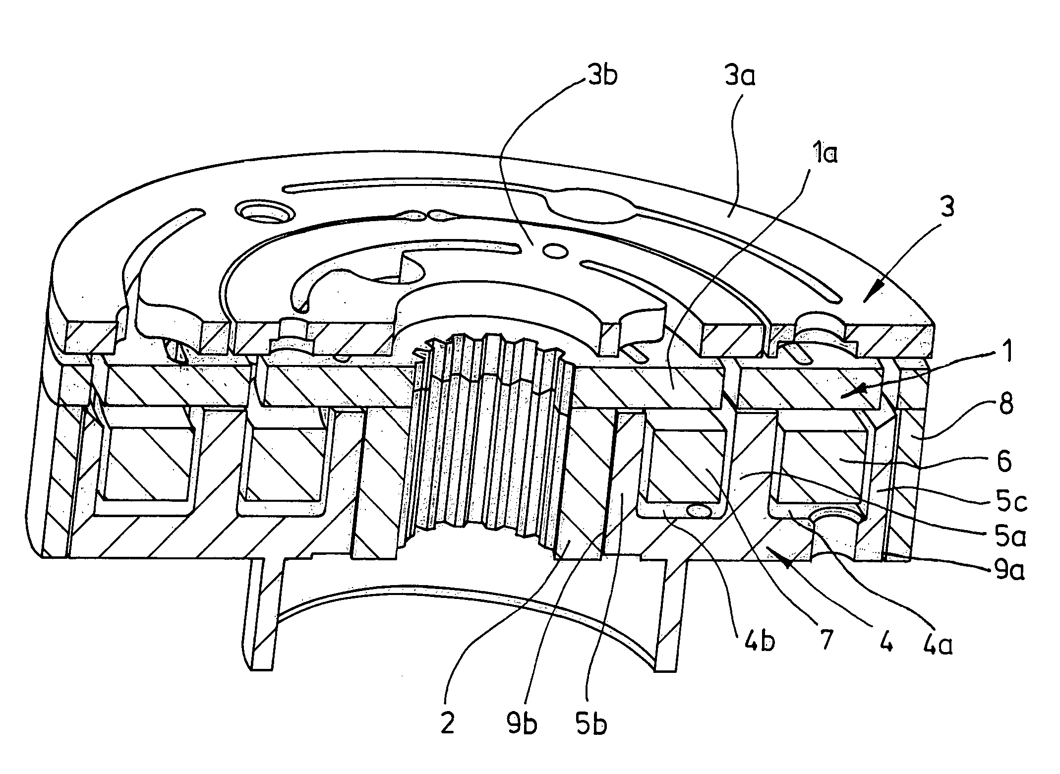
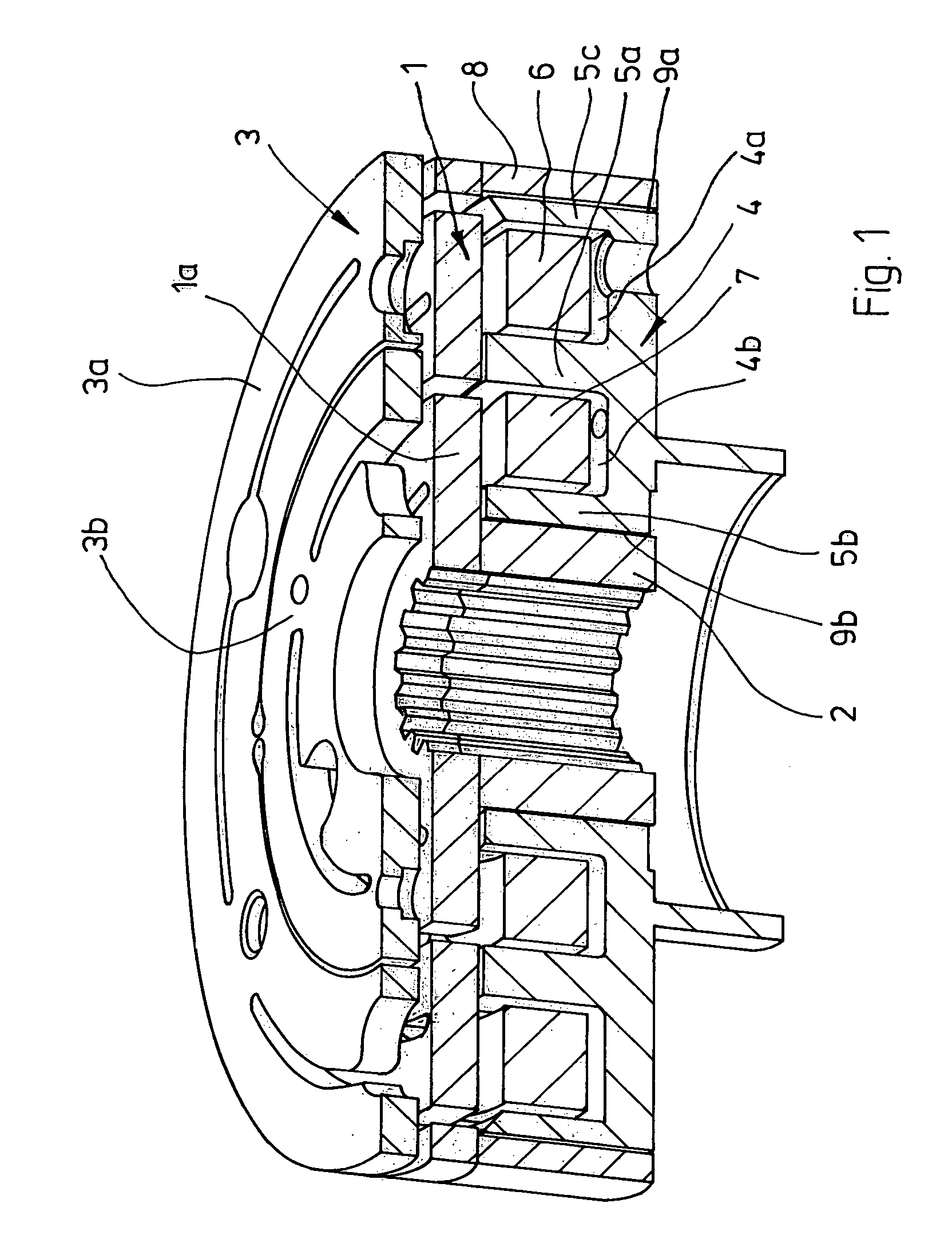
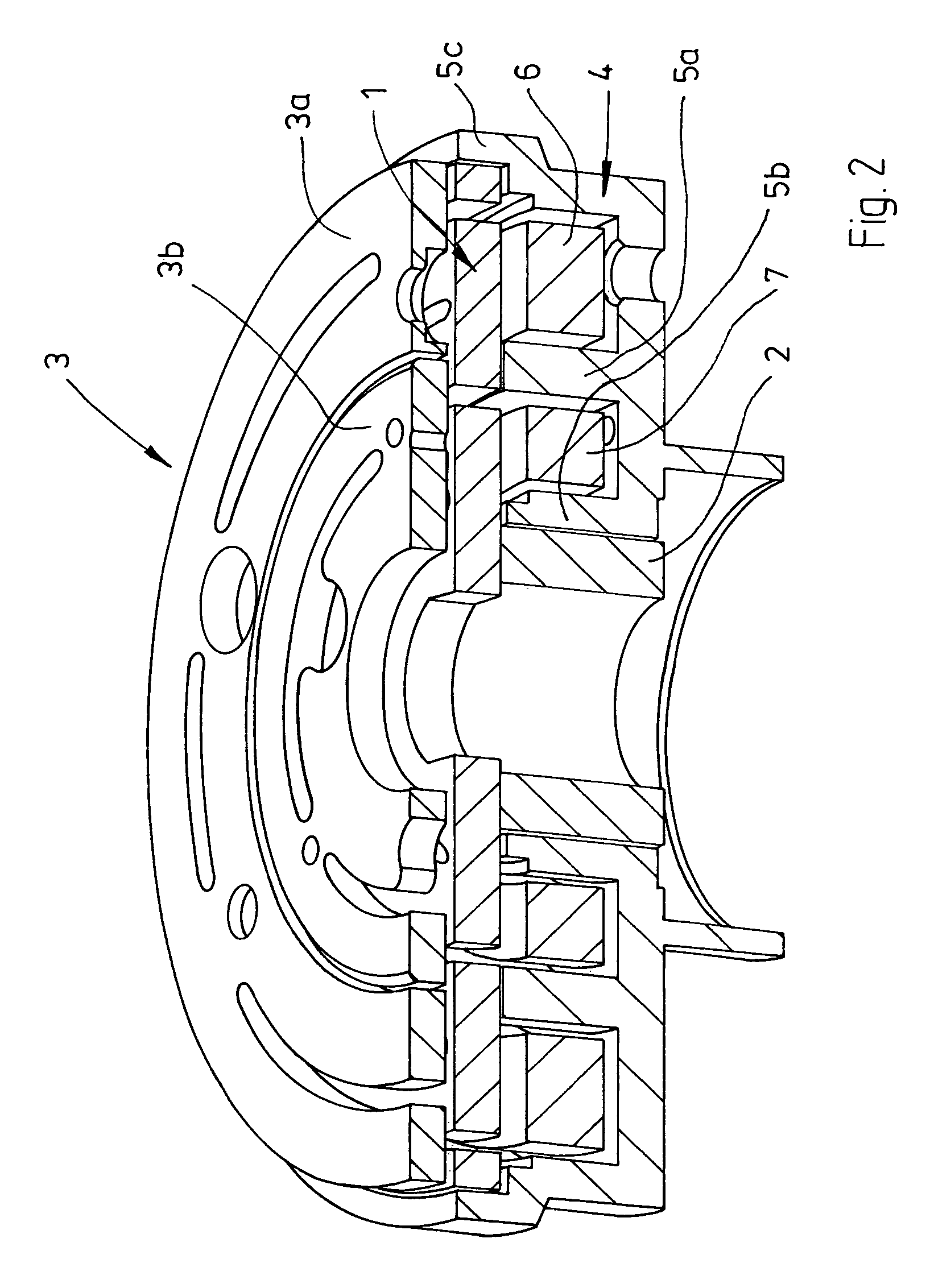
[0022]FIG. 1 depicts the important parts of a friction disk clutch. These include a rotor 1 which has an armature disk 3 spatially opposite it. The rotor has a shaft section 2 which is preferably only frictionally connected to a rotor disk 1a. At the radially outer edge, the rotor also comprises an annular web 8 which runs in the axial direction. The web 8 is preferably not integrally formed with the rotor disk 1a but attached to the rotor disk 1a, for example by welding, in particular laser welding. A magnet-surrounding body 4 is provided between the shaft section 2 and the web 8 and has two annular slot regions 4a, 4b which contain solenoids 6, 7.

[0023]In order to produce a two-stage friction disk clutch, the armature disk 3 is divided into two annular sections 3a, 3b which are drawn toward the rotor disk 1a when correspondingly supplied with power. If the solenoid 6 is switched on, the armature disk section 3a is drawn toward the rotor disk 1a. If the solenoid is switched on, the...


PUM


Abstract

The invention proposes a rotor for a two-stage electromagnetically operated friction disk clutch which comprises two electromagnets and armature means which can be brought into contact with the rotor and are composed of a magnetically permeable material. According to the invention, there is no axial web, or at least no substantial axial web, which projects into the electromagnetic region in a manner arranged in the friction clutch on the rotor, between a radially outer edge region and a radially inner center region on the rotor. The invention also proposes an electromagnetically operated friction disk clutch which has a rotor of this type.

Description

[0001]This application claims the benefit under 35 USC 119(a)-(d) of German Application No. 10 2005 036 418.7, filed Jul. 29, 2005, the entirety of which is incorporated herein by reference.FIELD OF THE INVENTION[0002]The invention relates to a rotor for an electromagnetically operated friction disk clutch, and to an electromagnetically operated friction disk clutch.BACKGROUND OF THE INVENTION[0003]Friction disk clutches or rotors for friction disk clutches of the type mentioned in the introduction are already known in a very wide variety of forms.[0004]The rotors have webs which project regularly and axially and, as viewed in the radial direction, overlap magnet-surrounding means for electromagnets of the friction disk clutch. As a result, the desired field profile is achieved at an air gap between the magnet-surrounding means and rotor webs.[0005]Rotors of electromagnetic clutches are frequently produced on steel blanks. In this case, a so-called preturning contour is first produc...

Claims


Application Information

Patent Timeline
Patent Type & Authority Patents(United States)
IPC IPC(8): F16D27/10
CPCF16D27/112F16D2027/005F16D2027/008
Inventor JUERGENSMEYER, JANKRAFFT, RAINER
Owner LICOS TRUCKTEC
Learn More