Fluorescence biosensor

a biosensor and fluorescence technology, applied in biochemistry apparatus, spectrum investigation, photographic processes, etc., can solve the problems of inability to miniaturize, high cost, and complexity of the process of optimizing the focus of stimulating light sources (to compensate), so as to improve the sensitivity of fluorescence biosensors, and improve the sensitivity to fluorescent radiation

Active Publication Date: 2009-06-02
STMICROELECTRONICS (RES & DEV) LTD
View PDF6 Cites 14 Cited by
  • Summary
  • Abstract
  • Description
  • Claims
  • Application Information

AI Technical Summary

Benefits of technology

[0035]According to a seventh aspect of the invention there is provided a method of improving the sensitivity of a fluorescence biosensor comprising the steps of illuminating one or more fluorescent species with stimulating radiation for a first period of time, and disposing of charges generated in a photodetector by the stimulating radiation. The method may further comprise accumulating in a charge integrator over a second period of time, after the first period, the charge generated in the photodetector by fluorescent radiation emitted from the fluorescent species. These steps are cyclically repeated without resetting the charge integrator between cycles. The accumulating may be performed approximately 0.1 to 5 ns after the first period of the illuminating.
[0036]An advantage of the improved fluorescence biosensor is that there is an increased sensitivity to fluorescent radiation compared with conventional fluorescence biosensors. Consequently, the stimulating light source in the improved fluorescence biosensor does not need to stimulate fluorescent labels with as much power as conventional fluorescence biosensors. Thus, cheaper light sources can be used in the improved fluorescence biosensor compared with those of conventional fluorescence biosensors.
[0037]The fluorescence biosensor advantageously discriminates between stimulating radiation and fluorescent radiation directly on its photodetector's pixels. This eliminates the need for wavelength filtering, thereby reducing the size of the improved fluorescence biosensor and leading the way to a miniaturized Lab-on-Chip system. In addition, the removal of the need for expensive wavelength filtering, ensures that the fluorescence biosensor is cheaper to manufacture than conventional fluorescence biosensors.

Problems solved by technology

Unfortunately, prior art systems such as the Agilent 2100 bioanalyzer are typically large, very expensive and not amenable to miniaturization.
In addition, the process of optimizing the focus of the stimulating light source (to compensate for tilting of the specimen and / or non-flat surfaces) can be quite complicated.
Consequently, if a substrate contains a number of sensor elements (to detect multiple different analytes) the scanning time of the Agilent 2100 bioanalyzer may be quite long.
However, these wavelength discrimination systems are typically large and expensive.
Consequently, there is no practical impediment to scanning biosensor arrays with such larger pixels, wherein a charge integrator circuit as depicted in FIG. 4 is particularly suitable for processing the signals acquired by such enlarged pixels.

Method used


Image

  • Fluorescence biosensor
  • Fluorescence biosensor
  • Fluorescence biosensor

Examples


Embodiment Construction

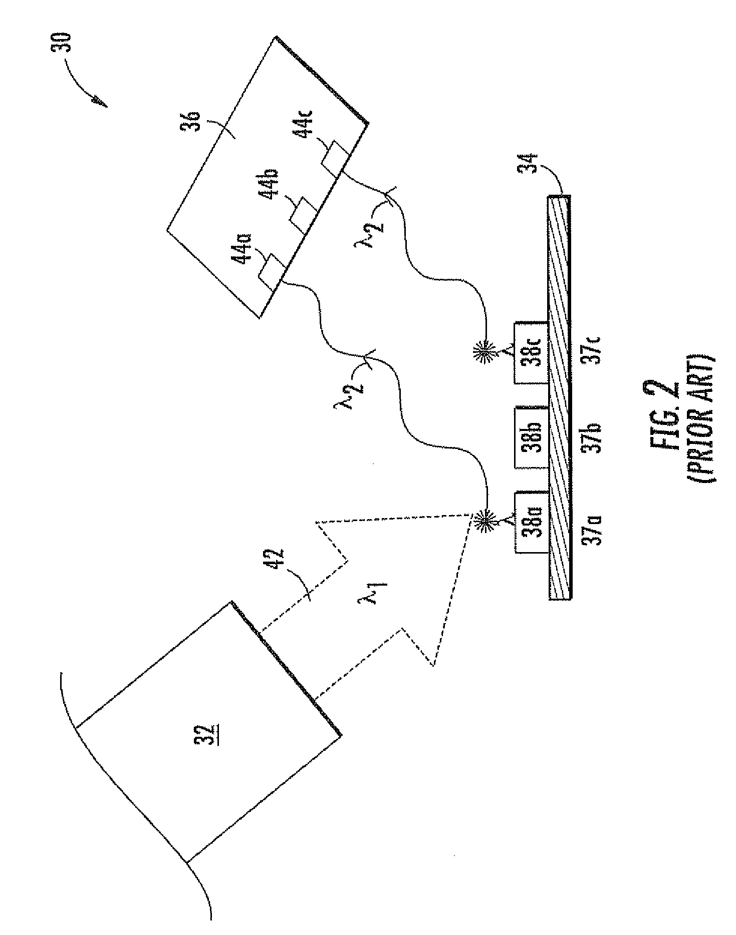
[0046]Referring to FIG. 5, a key feature of the fluorescence biosensor 100 is the repeated activation (by an activating signal φ1) of the stimulating light source 132 over a pre-defined period (known as the measurement period τ). The radiation from the stimulating light source 132 (i.e., the stimulating radiation λ1) stimulates the fluorescent labels 138 in the fluorescence biosensor 100 to repeatedly emit fluorescent radiation λ2 over the measurement period τ.

[0047]At the same time, the fluorescence biosensor 100 accumulates the small number of electrons produced in the biosensor's photodetector 136 by the repeated emissions of fluorescent radiation λ2. For the sake of simplicity, the photons of the stimulating radiation λ1 will be known as stimulating photons. Similarly, the photons of the fluorescent radiation λ2 will be known as fluorescent photons.

[0048]By accumulating the photogenerated electrons over the duration of the measurement period τ, the net photogenerated charge in t...


PUM

PropertyMeasurementUnit
timeaaaaaaaaaa
timeaaaaaaaaaa
fluorescenceaaaaaaaaaa

Abstract

A fluorescence detector includes a light source being positioned so that in use, radiation emitted therefrom falls on one or more fluorescing species, and a photodetector being switchably connectable between a charge integrator device and a charge disposal device. The photodetector is positionable to detect fluorescent radiation from the fluorescing species. A controller communicates with the light source and the photodetector, and is operable in a cyclic manner to activate the light source to emit radiation and connect the photodetector to the charge disposal device for a first period of time, and connect the photodetector to the charge integrator device for a second period of time after the first period. The charge integrator device is not reset from one cycle to the next.

Description

FIELD OF THE INVENTION[0001]The present invention relates to sensors, and in particular, to a fluorescence biosensor.BACKGROUND OF THE INVENTION[0002]Biosensors are analytical tools that detect the presence of a chemical or biochemical species in a complex mixture by combining the molecular recognition properties of biological macromolecules (e.g., enzymes, antibodies, DNA or even whole cells) with signal transduction mechanisms (e.g., optical or electrochemical) that couple ligand bindings with readily detectable physical changes.[0003]The optical signal transduction mechanisms employed by biosensors are based on absorption spectroscopy (ultraviolet (UV) to deep infrared (IR)), Raman or fluorescence spectroscopy. Fluorescence spectroscopy provides a particularly important detection mechanism because a number of biological species (including the green fluorescent protein (GFP), nucleic acids and flavine nucleotides) are naturally fluorescent. In addition, biological species that are...

Claims


Application Information

Patent Timeline
Patent Type & Authority Patents(United States)
IPC IPC(8): C12M1/34
CPCG01J3/02G01J3/027G01J3/2803G01J3/4406G01N21/6428G01N21/645G01J1/46
Inventor RAYNOR, JEFFREY
Owner STMICROELECTRONICS (RES & DEV) LTD
Why Eureka
Try Eureka