Hydraulic system for linear drives controlled by a displacer element

a technology of displacement control and linear drive, which is applied in the direction of fluid couplings, servomotors, couplings, etc., can solve the problems of poor energy utilization, poor control of hydraulic valves, and increased vibration in the implement, so as to reduce vibration, prevent undesirable pressure peaks in the system, and high energy efficiency

Inactive Publication Date: 2009-06-09
CNH BAUMASCHEN
View PDF6 Cites 31 Cited by
  • Summary
  • Abstract
  • Description
  • Claims
  • Application Information

AI Technical Summary

Benefits of technology

[0014]It can be advantageous that the low-pressure system is formed as an accumulator filling circuit with an accumulator-filling valve, a pump with hydraulic reservoir and a pressure-limiting valve. Such an arrangement of the low-pressure side is characterized by a particularly high energy-efficiency. The pump delivers only when the pressure in the low-pressure system falls below a set minimum pressure value. The accumulator filling circuit takes care of maintaining of a low-pressure level between adjustable limits. Such a low-pressure system can be formed centrally for the entire hydraulic system and supply all of the displacement-controlled hydraulic circuits in accordance with the invention.
[0015]A further embodiment of the hydraulic system in accordance with the invention is characterized in that the controllable shutoff valve is formed as a seat valve with 3/2-way pilot control. Furthermore it can be sensible, that the controllable shutoff valve is designed as a pneumatic continuous valve. With such a valve, the appropriate blocking function of the connection can be realized simply, without an overly jerky opening and closing of the valve occurring. In this manner undesirable pressure peaks in the system can be prevented.
[0016]It could be advantageous that further constantly controllable shutoff valves are provided for alternative and/or simultaneous control of further differential cylinders. As described above, through such valves further functions on the same high-pressure circuit can be implemented, as a result of which these operate always alternatively to each other. The shutoff valves are connected in such a way that the pump with the associated protective and equalization valves is connected to one differential cylinder or several connected together with the same function and supplies these with pressure medium.
[0017]A further embodiment of the invention envisages that

Problems solved by technology

The disadvantage of this valve-controlled hydraulic system is especially the poor utilization of energy.
In order to achieve the desired flows of pressure medium at the throttle edges of the valves, pressure differences are necessary, which in principle lead to high energy losses in the hydraulic valve controls.
It is not possible to utilize surpluses of energy on a consumer of the system in the form of potential energy or braking energy for other consumers in the system and thereby improve the efficiency of the system, which makes the development of heat in the system worse yet again.
A central pressure medium supply possesses in addition the disadvantage that where several consumers must be operated simultaneously, the volume flows are divided, which makes precise control and operation of the individual components more difficult.
Safety-relevant circuits, in which it must be ensured that individual consumers, e.g. the steering or brakes, always have sufficient pressure medium available, for example al

Method used


Image

  • Hydraulic system for linear drives controlled by a displacer element
  • Hydraulic system for linear drives controlled by a displacer element
  • Hydraulic system for linear drives controlled by a displacer element

Examples


Embodiment Construction

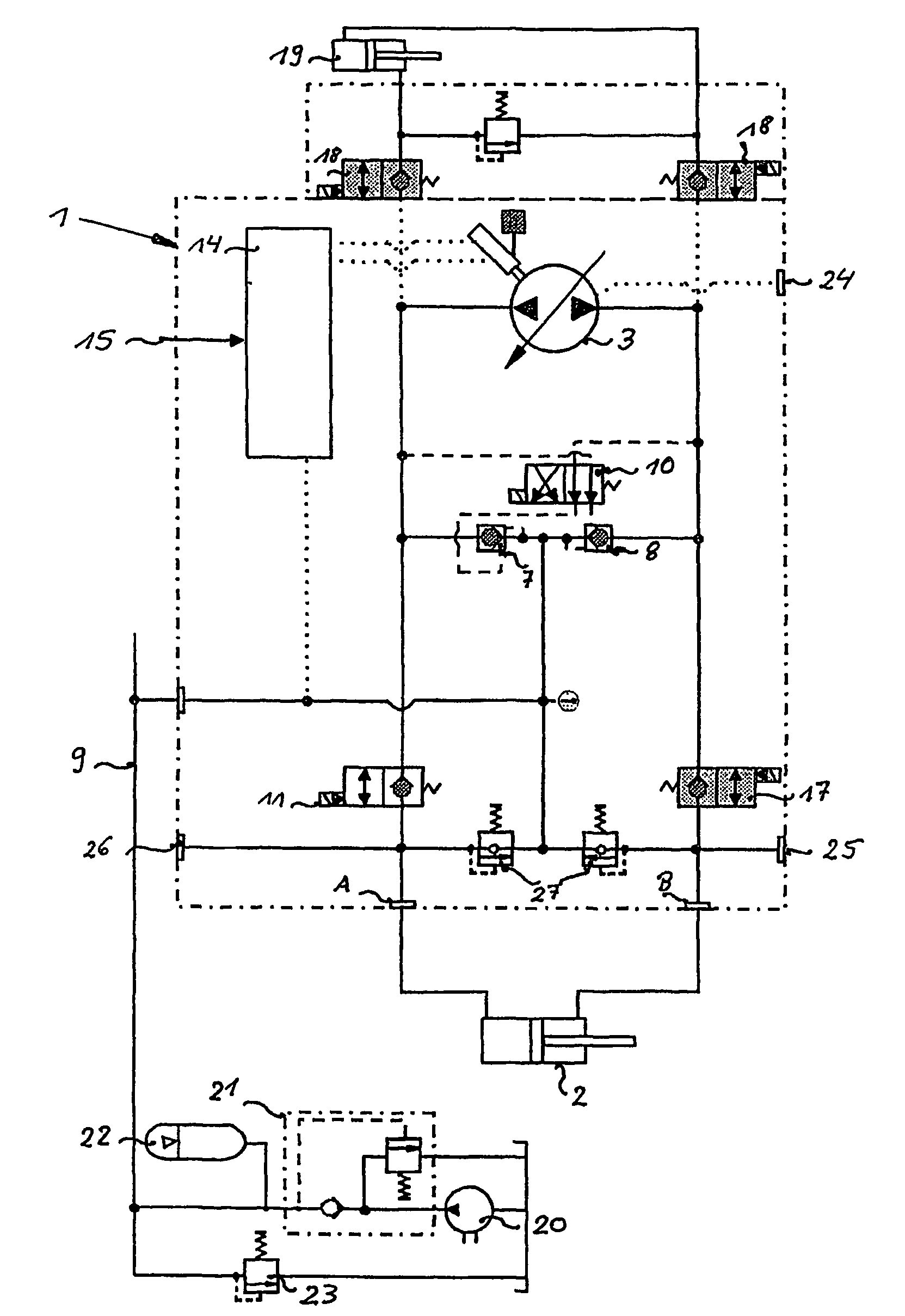
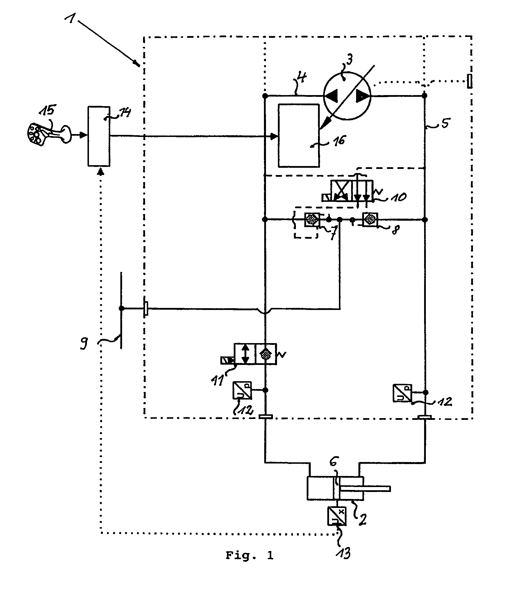
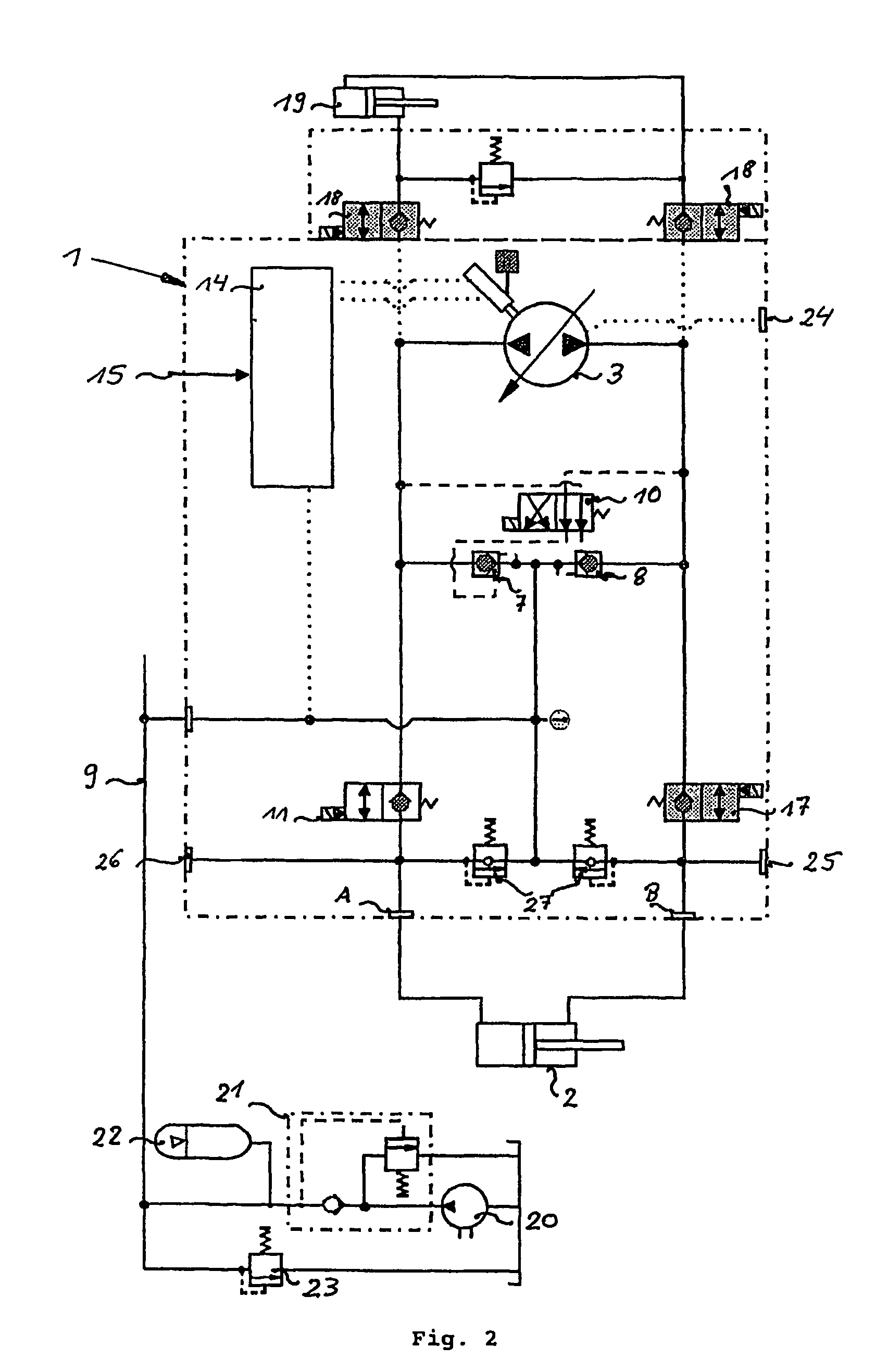
[0029]A hydraulic system generally designated by 1 serves to drive a hydraulic differential cylinder 2. A pump 3 with a variable delivery volume and reversal of the delivery direction is connected via two pipes 4 and 5 to the two connections of the differential cylinder 2. A volume flow delivered by pump 3 in one or the other direction leads to a movement of the piston 6 of the differential cylinder 2. As both chambers of the hydraulic differential cylinder 2 possess a different volume determined by the asymmetric design of the piston 6 and the piston rod, during the movement of the piston 6 a different quantity of pressure medium is given up by one side than is taken up by the other side. In order to reconcile this difference, volume flow in the actual closed circuit between pump 3 and cylinder 2, this high-pressure circuit is connected to the low-pressure system 9 via two releasable non-return valves 7 and 8.

[0030]In the stationary case through the higher pressure, in one of the t...


PUM


Abstract

The invention concerns a hydraulic system for linear drives with a differential cylinder, in particular for mobile machines which through the use of displacement-control of the drives avoids the many and diverse disadvantages of the state of the art and renders possible a precise and energy-efficient control of linear drives with differential cylinders, and which is economical and simple to maintain and which can be well integrated into the total hydraulic system of such machines.

Description

FIELD OF THE INVENTION[0001]The present invention concerns a hydraulic system for positive-displacement-controlled linear drives, in particular for mobile machines with at least one differential cylinder, at least one high pressure circuit, which comprises at least one pump with variable delivery volume and is connected to a low pressure system by at least two releasable non-return-valves.BACKGROUND OF THE INVENTION[0002]Current hydraulic systems for mobile machines are based predominantly upon valve-controlled principles. With them the various hydraulic consumers, such as drives for the working hydraulics, steering, braking etc. are controlled by means of hydraulically or electro-hydraulically driven valve arrangements. Usually one or more central pressure supplies are employed for this, frequently in the form of load-sensing pumps, which provide the flows of pressure medium, which through arrangements of one or more valves influence the desired behavior of the hydraulic consumers....

Claims


Application Information

Patent Timeline
IPC IPC(8): F16D31/02F15B7/00F15B21/08
CPCF15B7/006F15B21/082
Inventor IVANTYSYNOVA, MONIKARAHMFELD, ROBERTLAUTNER, ERIKWEBER, JURGEN
Owner CNH BAUMASCHEN
Why Eureka
Try Eureka