Molding apparatus and method

Inactive Publication Date: 2009-06-09
COLUMBUS STEEL CASTINGS
View PDF2 Cites 25 Cited by
  • Summary
  • Abstract
  • Description
  • Claims
  • Application Information

AI Technical Summary

Benefits of technology

[0004]The present invention disclosed herein addresses traditional shortcomings of green sand molding by employing a variation on the phenolic urethane cold-box system to produce stronger molds and cores of higher dimensional accuracy. Although other core and mold making methods may be embodied within this invention, the cold-box system employs molding sand impregnated with phenolic urethane “no-bake” (hence “cold-box”) binders typically used to form molding cores. One principal advantage of using a phenolic urethane binder is that it can be rapidly catalyzed at room temperature by means of an amine vapor that is blown through the core sand to produce durable cores. Removal of the core from the cast part is made easier by carefully controlling the composition of the phenolic urethane impregnated sand and curing conditions. This invention extends the use of the cold-box system to include forming the mold as well as the core resulting in a sturdy core mold assembly that has superior dimensional stability as well as improved structural integrity that permits more aggressive handling

Problems solved by technology

However, significant disadvantages are associated with the green sand method, some of which are the need for careful handling of the mold assembly due to the relative fragility of the green sand, as well as undesirable dimensional variations between castings associated with mold cavity and core misalignment and pattern wear.
Additionally, green sand molding t

Method used


Image

  • Molding apparatus and method
  • Molding apparatus and method
  • Molding apparatus and method

Examples


Embodiment Construction

)

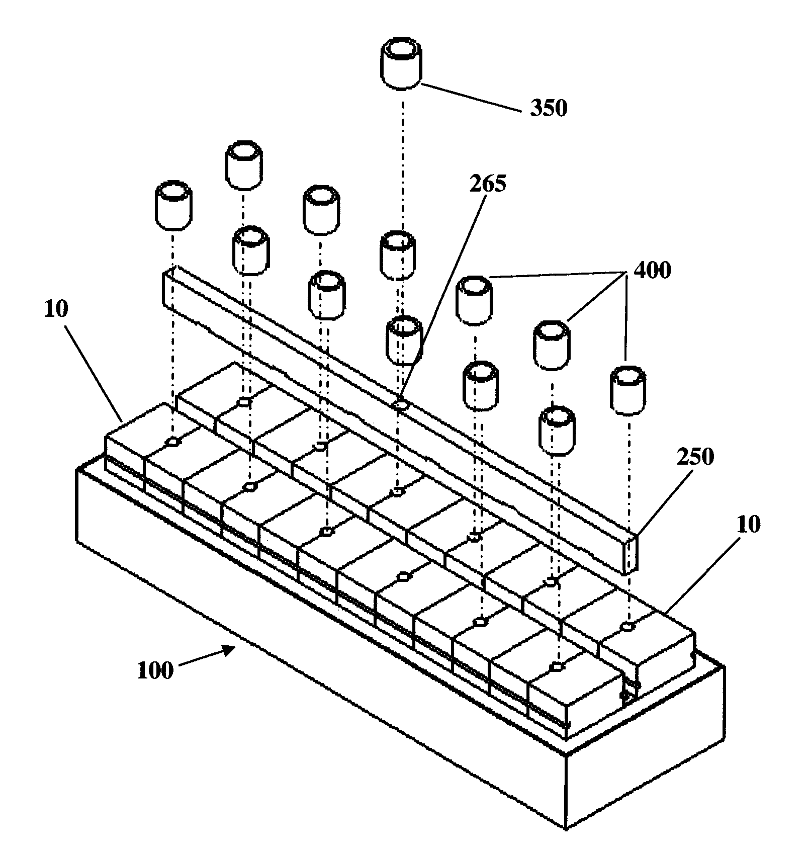
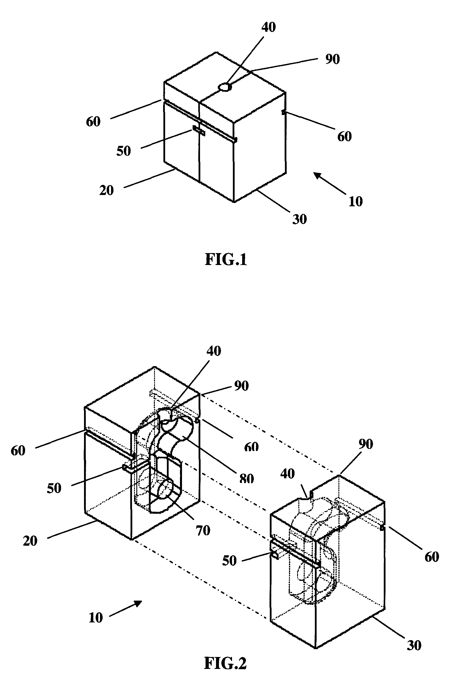
[0023]The present invention is directed to casting technology. In addition, the present invention teaches a core mold assembly unit apparatus as well as a method of embodying a plurality of core mold assembly units within an external cope and external drag flask assembly to produce a plurality of independently formed parts. FIG. 1 shows an example of a core mold assembly unit 10, which comprises a core mold left half 20, a core mold right half 30, a riser vent 40, a filling gate 50, a handling groove or grooves 60, and split line 90.

[0024]FIG. 2 further illustrates an example of a core mold assembly unit 10 separated into core mold assembly unit left half 20 and core mold assembly unit right half 30 along a split line 90 to show the internal details of core assembly 70 and mold cavity 80, which in this example, represents the molding features of a railroad car connector knuckle. In one preferred embodiment, the core mold assembly unit 10 is comprised of phenolic urethane treated mo...


PUM

PropertyMeasurementUnit
Dimensional stabilityaaaaaaaaaa
Shapeaaaaaaaaaa
Castabilityaaaaaaaaaa

Abstract

This invention teaches an improved method and apparatus to make metal alloy castings, such as railroad car connector knuckles. One embodiment of the invention comprises a plurality of core mold assembly units contained within a single molding flask, wherein the mold units are filled with molten metal by way of a common runner and riser system. The said core mold assembly elements may be further comprised of a mold and core assembly formed of the same material, such as phenolic urethane impregnated sand, which is used to accurately replicate the desired shape of a final desired product. This invention eliminates the need to carefully gauge a plurality of part patterns within a single mold flask and reduces the potential for loss of parts, for example by cold shunting, by segregating each part to its own mold isolated mold unit. Such a method and apparatus allows a plurality of parts to be cast in a more accurate way, producing less scrap, improving part dimensional stability, and in some cases, reducing the number of cores needed.

Description

BACKGROUND AND SUMMARY OF THE INVENTION[0001]The present invention relates generally to methods and apparatus for use in casting, particularly to more efficiently producing castings of such items as railroad car connector knuckles.[0002]Casting methods currently used to produce items of metal alloys employ molding techniques that replicate the interior and exterior features of a desired part. Such methods comprise an exterior mold that replicates the external surface features of the desired part, while a core or cores are used to replicate interior cavities and surfaces if such parts embody hollow or reentrant features. The mold and cores are produced from a pattern of the part and are assembled together within containers called “flasks” to produce a cavity that replicates the volume and surface features of the desired part. The mold flask is usually split into two separate components; an upper component traditionally called the “cope” and a lower component called the “drag.” A patt...

Claims


Application Information

Patent Timeline
IPC IPC(8): B22C9/20B22C21/00
CPCB22C9/20B22C21/00
Inventor PINKSTOCK, STEVEN R.HOLMAN, CRAIG A.CONCITIS, JOHN C.POE, RONALD A.
Owner COLUMBUS STEEL CASTINGS
Why Eureka
Try Eureka