
Multiphase clock generator

a generator and multi-phase technology, applied in the field of electronic circuits, can solve the problems of timing jitter between the phases of clock signals, power and chip area consumption of multiple-phase interpolators, and large area consumption of phase interpolators, so as to reduce timing jitter, and consume less power and chip area

Inactive Publication Date: 2009-06-09
INTEGRATED DEVICE TECH INC
View PDF15 Cites 29 Cited by
  • Summary
  • Abstract
  • Description
  • Claims
  • Application Information

AI Technical Summary

Benefits of technology

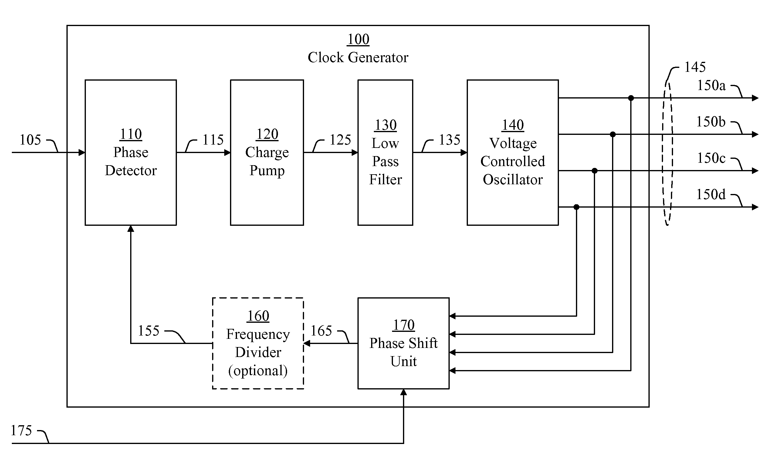
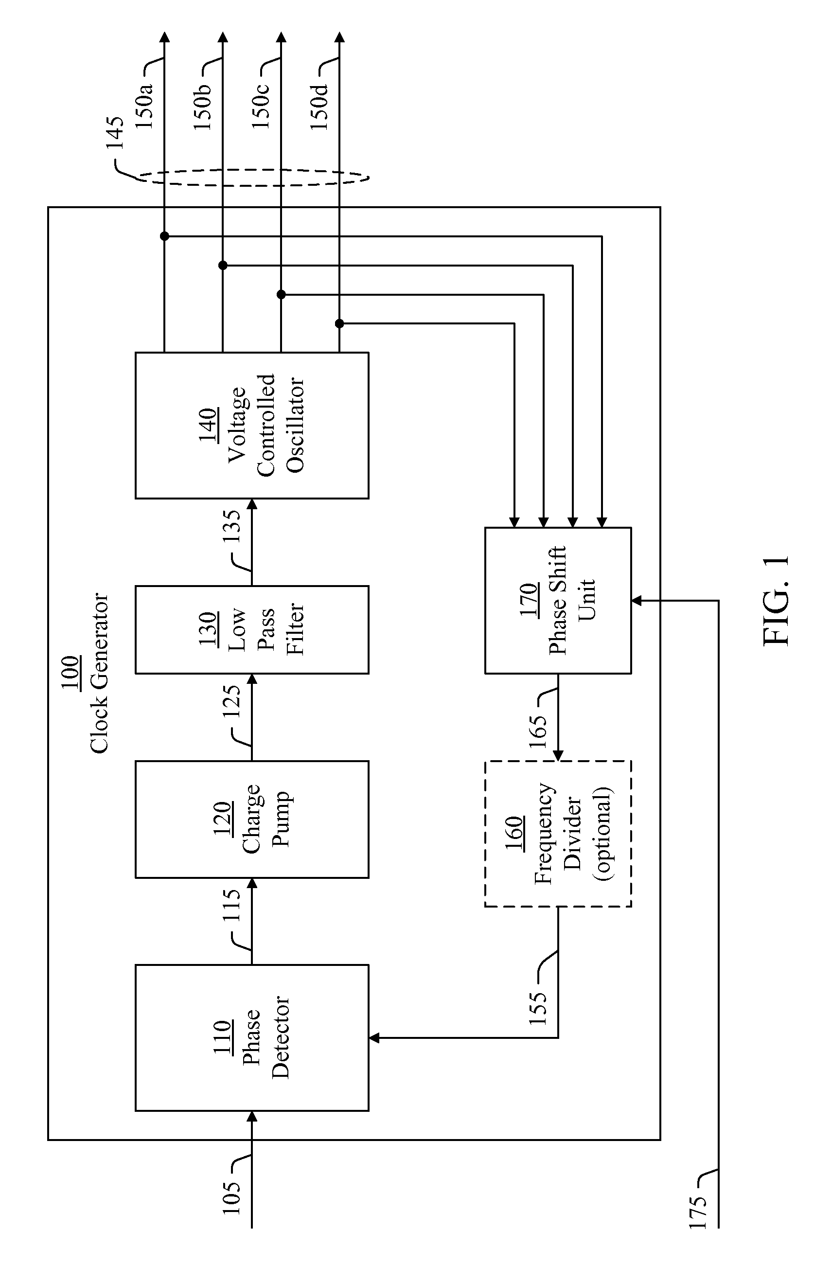
[0008]In various embodiments, a clock generator generates multiple clock signals, based on an input signal, and shifts the phases of the clock signals relative to a phase of the input signal, based on a control signal. The clock generator includes a phase locked loop that includes a phase shift unit. The phase shift unit selects some of the clock signals based on the control signal and generates a feedback signal of the phase locked loop based on the selected clock signals. The feedback signal has a phase based on the phases of the selected clock signals. The phase locked loop aligns the phase of the feedback signal with the phase of the input signal. In this process, the phase locked loop shifts the phase of each of the clock signals relative to the phase of the input signal. By including the phase shift unit in the phase locked loop, the clock generator need not have an individual phase shift unit for each of the clock signals. Consequently, the clock generator consumes less power and area. In particular, the clock generator consumes less power and chip area in an integrated circuit. Further, using a single phase shift unit in the clock generator reduces timing jitter between the phases of the clock signals generated by the clock generator, which improves the accuracy of the clock generator.

Problems solved by technology

Although phase interpolators have been successfully used to adjust the phases of clock signals generated in a receiver, phase interpolators generally consume a considerable amount of power and area in those applications in which multiple phase interpolators are used.
In particular, multiple phase interpolators consume a considerable amount of power and chip area in integrated circuit applications.
Moreover, performance variations among multiple phase interpolators in a receiver tend to cause timing jitter between the phases of the clock signals generated by the phase interpolators.
The timing jitter decreases the accuracy of the clock generator in maintaining the phase relationships of the generated clock signals, which decreases performance of the receiver.

Method used


Image

  • Multiphase clock generator
  • Multiphase clock generator
  • Multiphase clock generator

Examples


Embodiment Construction

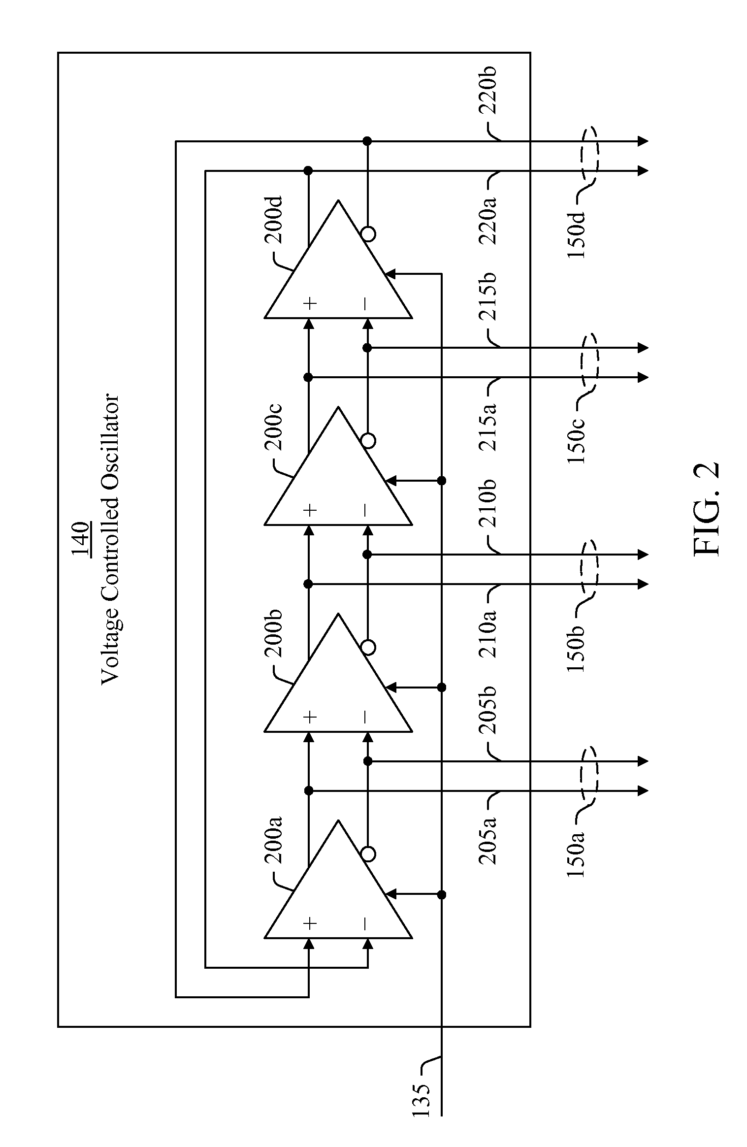
[0022]In various embodiments, a clock generator generates multiple clock signals based on an input signal and a feedback signal. The multiple clock signals differ in phase from each other and each has a phase relationship with the input signal. The clock generator selects clock signals based on a control signal and determines a phase of the feedback signal. The phase of the feedback signal is based on the phases of the selected clock signals. Further, the clock generator adjusts the phase relationships between the multiple clock signals and the input clock signal based on the feedback signal. In this way, the clock generator adjusts the phases of the multiple clock signals based on the control signal.

[0023]FIG. 1 illustrates clock generator 100, in accordance with an embodiment of the present invention. The clock generator 100 receives an input signal 105 and generates a multiphase clock signal 145 based on the input signal 105 and a control signal 175. Each of the input signal 105 ...


PUM


Abstract

A clock generator generates multiple clock signals based on an input signal and adjusts the phases of the clock signals relative to a phase of the input signal, based on a control signal. The clock generator includes a phase locked loop that includes a phase shift unit. The phase shift unit selects some of the clock signals based on the control signal and generates a feedback signal based on the selected clock signals. The feedback signal has a phase based on the phases of the selected clock signals. The phase locked loop aligns the phase of the feedback signal with the phase of the input signal. In this process, the phase locked loop shifts the phase of each of the clock signals relative to the phase of the input signal.

Description

BACKGROUND[0001]1. Field of the Invention[0002]The present invention generally relates to electronic circuits for generating clock signals, and more particularly to multiphase clock generators.[0003]2. Description of Related Art[0004]High-speed serial communication systems transmit and receive data in serial data streams. A serial data stream is a sequence of digital pulses that represents data as a sequence of binary values. A transmitter in the serial communication system uses a clock signal to encode data into a serial data stream and transmits the serial data stream to a receiver in the serial communication system. The receiver generates a clock signal having the same frequency as the clock signal in the transmitter and uses the clock signal to extract and reconstruct the data from the serial data stream.[0005]Some receivers include a clock generator that extracts and reconstructs a clock signal from the serial data stream. The reconstructed clock signal has the same frequency a...

Claims


Application Information

Patent Timeline
Patent Type & Authority Patents(United States)
IPC IPC(8): H03L7/06
CPCH03D7/1441H03K3/0322H03K5/13H03L7/0995H03L7/0996H03D7/1458H03L7/081H03K2005/00052H03K2005/00286H03L7/18H03D2200/0084
Inventor XU, CHAOFANG, AL XUEFENG
Owner INTEGRATED DEVICE TECH INC
Learn More