Backprojection reconstruction method for CT imaging

a reconstruction method and image technology, applied in tomography, instruments, nuclear engineering, etc., can solve the problems of x-ray dose to which the subject is exposed, application is particularly challenging, and cannot be used with this cra method intravenously, so as to increase the time resolution of the study, increase the snr of each image frame, and improve the effect of image reconstruction

Active Publication Date: 2009-06-09
WISCONSIN ALUMNI RES FOUND
View PDF20 Cites 87 Cited by
  • Summary
  • Abstract
  • Description
  • Claims
  • Application Information

AI Technical Summary

Benefits of technology

[0012]The present invention is a new method for reconstructing CT images, and particularly, an improved backprojection method. A composite image is acquired and reconstructed to provide a priori knowledge of the subject being imaged. This composite image is used during the backprojection of acquired images to weight the distribution of the back projected attenuation data. As a result, quality CT images can be reconstructed using fewer projection views of the subject, or using projection views acquired with a lower x-ray dose.
[0019]Another discovery of the present invention is that there are a number of clinical CT applications in which a priori information is available and a composite image can be reconstructed and used to enhance the reconstruction of images. When a series of time-resolved images are acquired in a dynamic study, each image frame may be reconstructed using a very limited set of acquired views in order to increase the time resolution of the study. To employ the highly constrained backprojection reconstruction method of the present invention, each such set of image frame views is interleaved with the views acquired for other image frames. After a number of image frames have been acquired, a sufficient number of different, interleaved views are available to reconstruct a quality composite image.
[0020]Another objective of the present invention is to enable an image to be acquired with a lower x-ray dose without significant loss of image SNR. By using a high SNR composite image in the highly constrained backprojection method of the present invention, the SNR of an image frame reconstructed from a lower dose set of projection views is significantly increased; For example, in a perfusion study in which contrast agent flowing into tissues is repeatedly imaged, a high SNR composite image may be acquired and a series of low dose image frames may be acquired during the study. By using the high SNR composite image to reconstruct each image frame, the SNR of each image frame is substantially increased.

Problems solved by technology

This application is particularly challenging when imaging coronary arteries or other vessels that require cardiac gating to suppress motion artifacts.
These streak artifacts preclude the use of this CRA method for intravenous angiography because of the reduced vasculature contrast provided by this contrast injection method.
Another issue with x-ray CT is the x-ray dose to which the subject is exposed during the scan.

Method used


Image

  • Backprojection reconstruction method for CT imaging
  • Backprojection reconstruction method for CT imaging
  • Backprojection reconstruction method for CT imaging

Examples


second embodiment

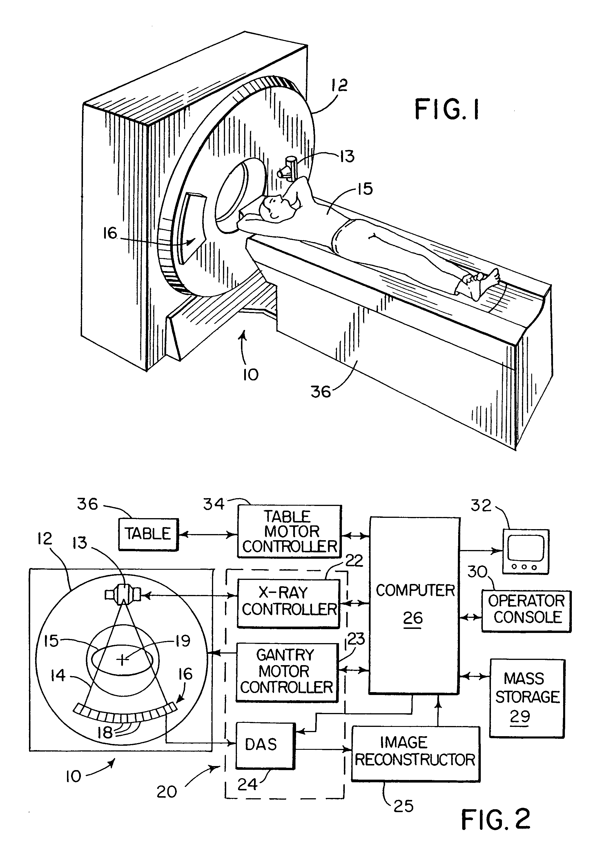
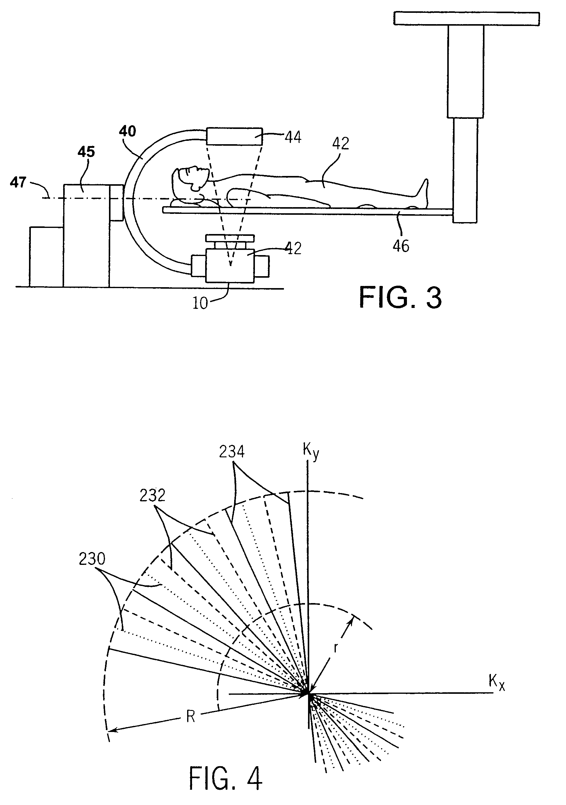
[0041]Referring to FIG. 3, a CT scanner which may employ the present invention comprises a C-arm 40 to which the two-dimensional detector 44 and X-ray source 42 are mounted. Here, again the patient 42 is positioned on a table 46. The C-arm 40 is rotationally mounted to a base 45, and data for the generation of three-dimensional images is obtained by rotating the X-ray source 42 and detector 44 around a defined axis 47. CT scanners of the type shown in FIG. 3 are particularly useful in angiography, as described in Use of a C-Arm system to generate True 3D Computed Tomography Rotational Angiograms; Preliminary in vitro and In vivo Results. R. Fahrig, S. Lownie, and D W Holdsworth, AJNR 18:1507-154, September 1997.

[0042]In the above described CT system a single x-ray source is revolved around the subject during a scan and the time resolution of each acquired image frame is limited by the time required to rotate the gantry through a substantial angle. This is necessary when an under-sam...

first embodiment

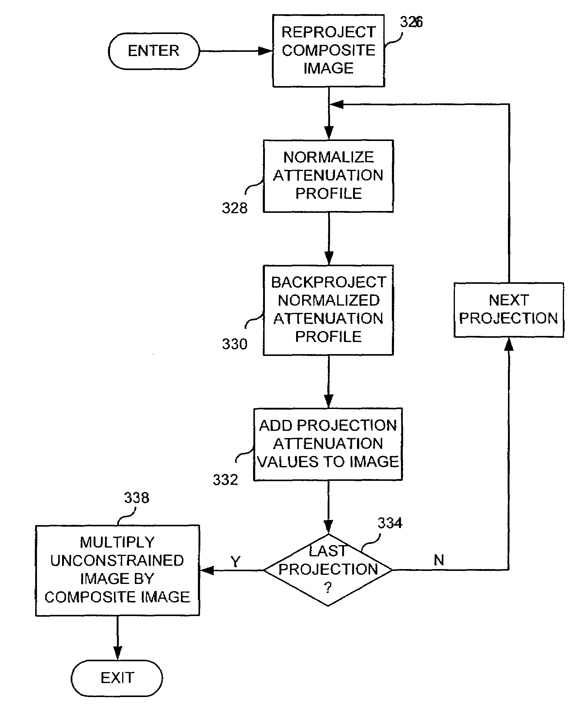
[0069]Prior to reconstructing the perfusion images a high resolution composite image is reconstructed as indicated at process block 412. This is a conventional filtered backprojection reconstruction using the difference projection views from all of the acquired image frames. Since the image frames are acquired at interleaved view angles in the first embodiment, collectively they provide a complete sampling of Radon space and an artifact-free, high SNR composite image can be produced with a standard reconstruction method. In the second approach described above the corresponding low-dose views acquired for each image frame are averaged to provide a higher SNR composite image than would otherwise be produced from one complete set of low dose views.

[0070]The series of time resolved perfusion image frames are then reconstructed and displayed. A loop is entered in which the limited set of difference views that comprise an image frame are backprojected using the highly constrained method d...


PUM


Abstract

Two-dimensional or three-dimensional, time-resolved CT frame images are acquired during a dynamic study of a subject. A composite image is produced and this is used to reconstruct each CT frame image by weighting the backprojection of each projection view acquired for that image frame by the corresponding value in the composite image. This weighted backprojection enables artifact-free image frames to be produced with far fewer projection views of the subject. The composite image may be reconstructed from views acquired separately, or it may be produced by combining views acquired during the course of the dynamic study.

Description

CROSS-REFERENCE TO RELATED APPLICATIONS[0001]This application is based on U.S. Provisional Patent Application Ser. No. 60 / 697,607 filed on Jul. 8, 2005 and entitled “BACKPROJECTION RECONSTRUCTION METHOD FOR UNDERSAMPLED TIME-RESOLVED MR IMAGING”, U.S. Provisional Pat. Appln. Ser. No. 60 / 716,865 filed on Sep. 14, 2005 and entitled “Backprojection Reconstruction Method For CT Imaging”; and U.S. Provisional Patent Application Ser. No. 60 / 739,554 filed on Nov. 23, 2005 and entitled “Backprojection Reconstruction Method For Low Dose CT Imaging”.STATEMENT REGARDING FEDERALLY SPONSORED RESEARCH[0002]This invention was made with government support under Grant No. HL072260 awarded by the National Institute of Health. The United States Government has certain rights in this invention.BACKGROUND OF THE INVENTION[0003]The present invention relates to computed tomography, and more particularly, to a method and apparatus for reconstructing an image from projection data acquired using a computed to...

Claims


Application Information

Patent Timeline
Patent Type & Authority Patents(United States)
IPC IPC(8): A61B6/03
CPCG06T11/006A61B6/507G06T2211/412G06T2211/424Y10S378/901
Inventor MISTRETTA, CHARLES A.
Owner WISCONSIN ALUMNI RES FOUND
Why Eureka
Try Eureka