
Raman amplifier, optical repeater, and raman amplification method

a raman amplifier and optical repeater technology, applied in the field of raman amplifiers and optical repeaters, can solve the problems of increasing amplification noise, difficult to use raman amplifiers, and worsening flatness, so as to achieve widening of the raman gain band, low loss, and high output

Inactive Publication Date: 2009-06-16
FURUKAWA ELECTRIC CO LTD
View PDF71 Cites 10 Cited by
  • Summary
  • Abstract
  • Description
  • Claims
  • Application Information

AI Technical Summary

Benefits of technology

[0018]Another object of the present invention is to provide a Raman amplifier which can obtain required gain and can reduce wavelength dependency of gain to the extent that usage of a gain flattening filter is not required and which can be used in a band of EDFA.
[0045]According to a twenty-ninth aspect of the present invention, in a Raman amplification method by stimulated Raman scattering in an optical fiber through which two or more pumping lights having different central wavelengths and said optical signals are propagated, the pumping power launched into said optical fiber increases as the central wavelengths of said pumping lights is shorter.

Problems solved by technology

Accordingly, when the flattening is realized by a gain flattening filter having fixed loss profile, if the gain of the EDFA is changed, the flatness will be worsened.
Increase amplification noise caused by the stimulated Brillouin scattering is one of the problems which makes it difficult to use the Raman amplifier.
Furthermore, enlargement of the gain band is required in the Raman amplifier.
However, this patent does not disclose concrete values of the wavelength interval.
By the way, on designing the optical repeater, it is required that a repeater input level, a repeater output level and a dispersion compensating amount (loss in the dispersion compensating fiber A) be set properly, and, there is limitation that the input level of the dispersion compensating fiber A has an upper limit, because, when the input power to the dispersion compensating fiber A is increased, influence of non-linear effect in the dispersion compensating fiber A is also increased, thereby deteriorating the transmission wave form considerably.
The noise property in such a system is deeply associated with the loss Ld [dB] in the dispersion compensating fiber A, and it is known that the greater the loss the more the noise property is worsened.
In this method, although the gain flatness is not changed, an additional insertion loss worsens the noise property.
In the optical fiber communication system, although the Er doped optical fiber amplifiers have widely been used, the Er doped optical fiber amplifier also arises several problems.
Further, the Raman amplifier also has problems that, since output of ordinary semiconductor laser is about 100 to 200 mW, gain obtained is relatively small, and that the gain is sensitive to change in power or wavelength of the pumping light.
Further, such shifting of the central wavelength is not preferable because such shifting causes change in joining loss of a WDM coupler for multiplexing the pumping light.
In addition, the optical repeater also has a problem that the Er doped optical fiber amplifiers B, C must be re-designed for each system.
Further, the deterioration of the noise property due to insertion of the dispersion compensating fiber is hard to be eliminated in the present systems.
Although the length of the fiber can be shortened by using an optical fiber having great non-linearity, in the optical fiber having great non-linearity, it is difficult to reduce the transmission loss caused by (OH) generally having a band of 1380 nm, and Rayleigh scattering coefficient becomes great considerably in comparison with the communication fiber, with the result that the difference between the maximum and minimum values of fiber loss within the above-mentioned wavelength range becomes very great such as 1.5 to 10 dB / km.
Thus, the wavelength division multiplexing signals cannot be uniformly amplified by using the pumping lights having the same intensities.

Method used


Image

  • Raman amplifier, optical repeater, and raman amplification method
  • Raman amplifier, optical repeater, and raman amplification method
  • Raman amplifier, optical repeater, and raman amplification method

Examples


fourth embodiment

of Optical Repeater

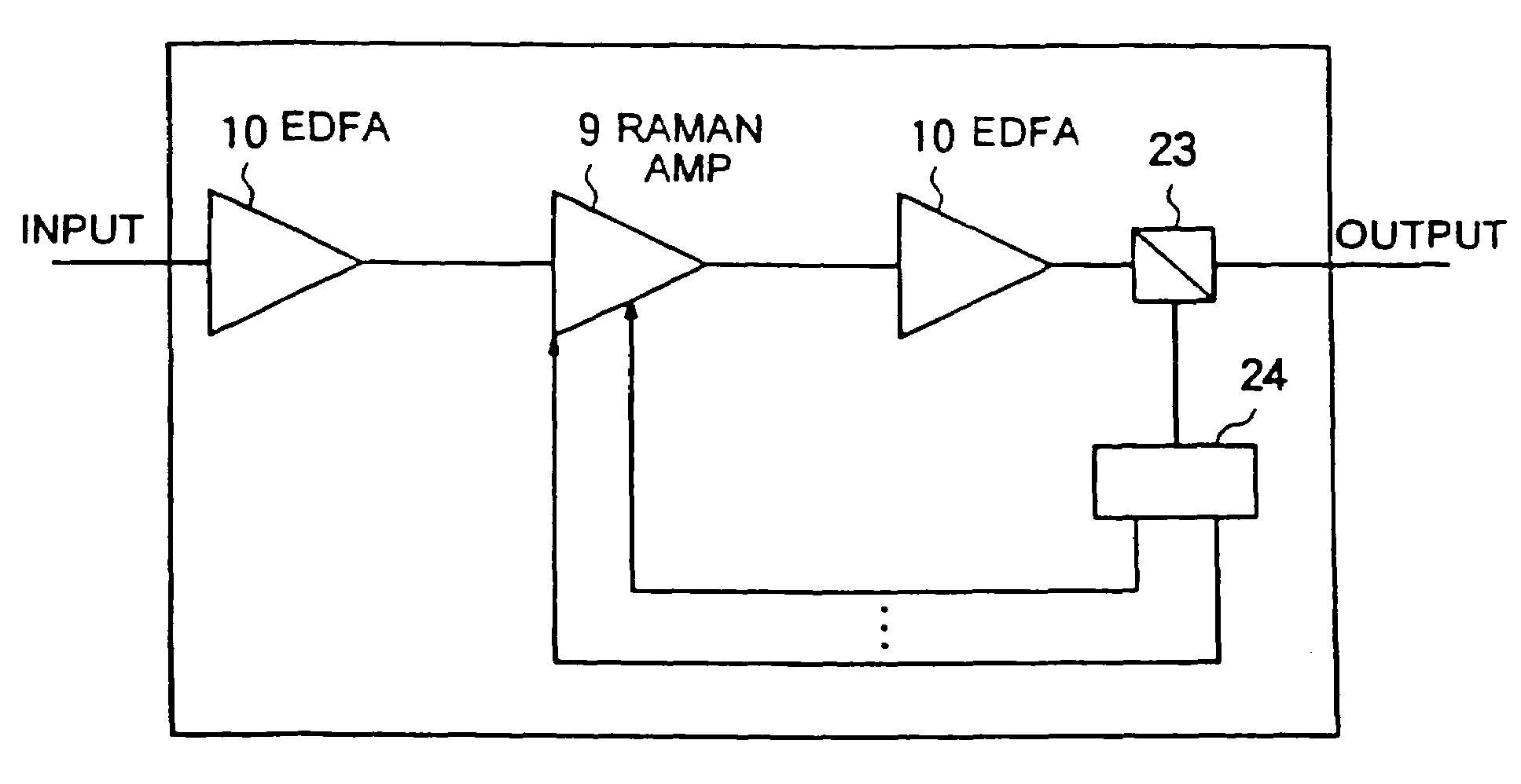
[0142]FIG. 10 shows an example that, in the embodiment shown in FIG. 9, a control means for adjusting the gain of the Raman amplifier 9 by monitoring the light level is also provided between the first EDFA 10 and the Raman amplifier 9. By using such control means, the pumping light can be controlled to keep the difference between the input and output levels of the Raman amplifier 9 constant, with the result that only the dispersion of the loss of the DCF can be compensated.

fifth embodiment

of Optical Repeater

[0143]FIG. 11 shows an example that, in the above-mentioned embodiment, the gain flattening monitor mechanism is shifted to the output end of the repeater and is used as a monitor for flattening the gain of the entire repeater. In this case, the first EDFA 10 and the second EDFA 10 may perform the gain constant control or the output constant control. The powers of the pumping lights are independently controlled to reduce the level deviation between the output signals at the output of the repeater.

Sixth Embodiment of Optical Repeater

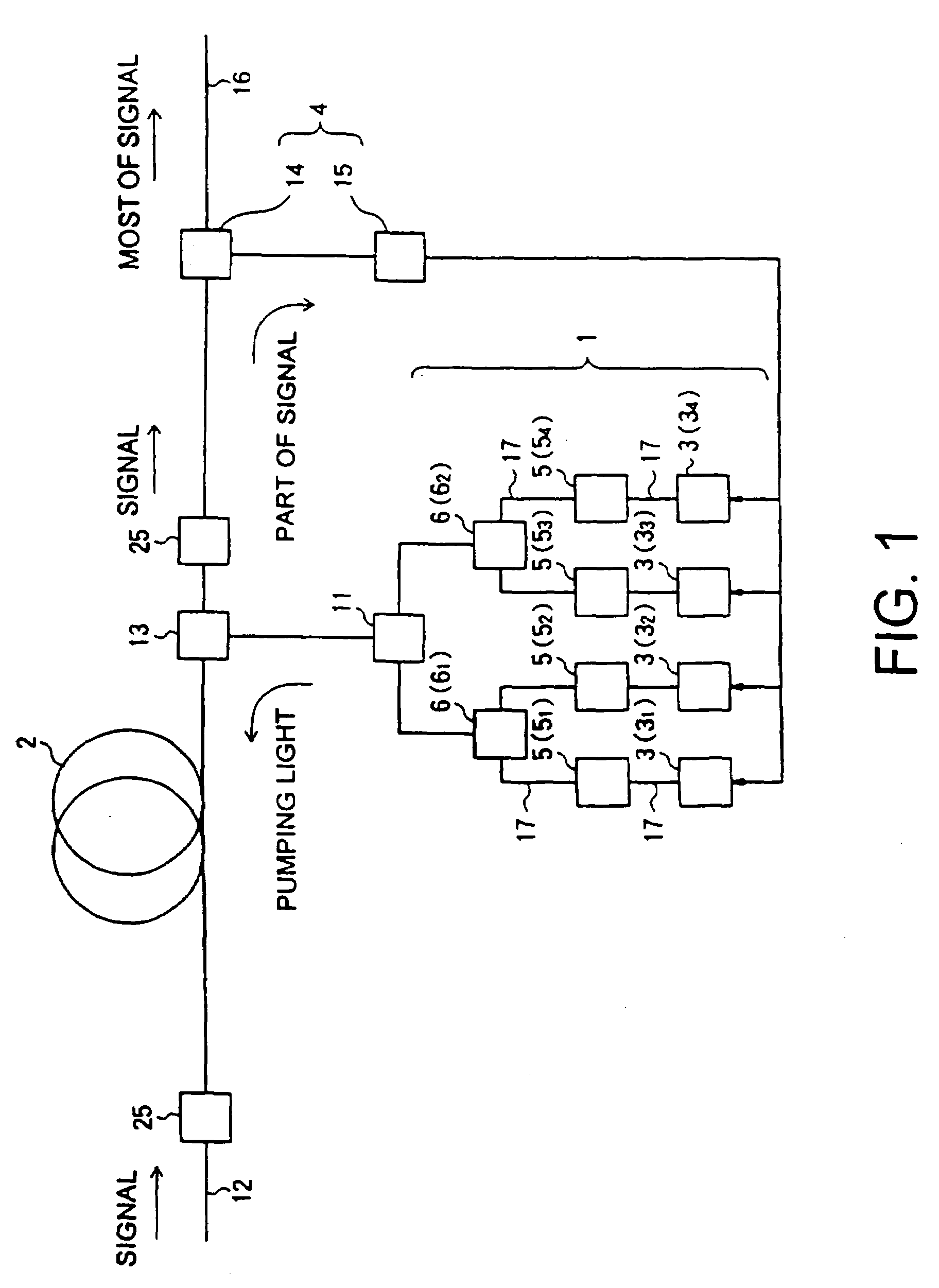
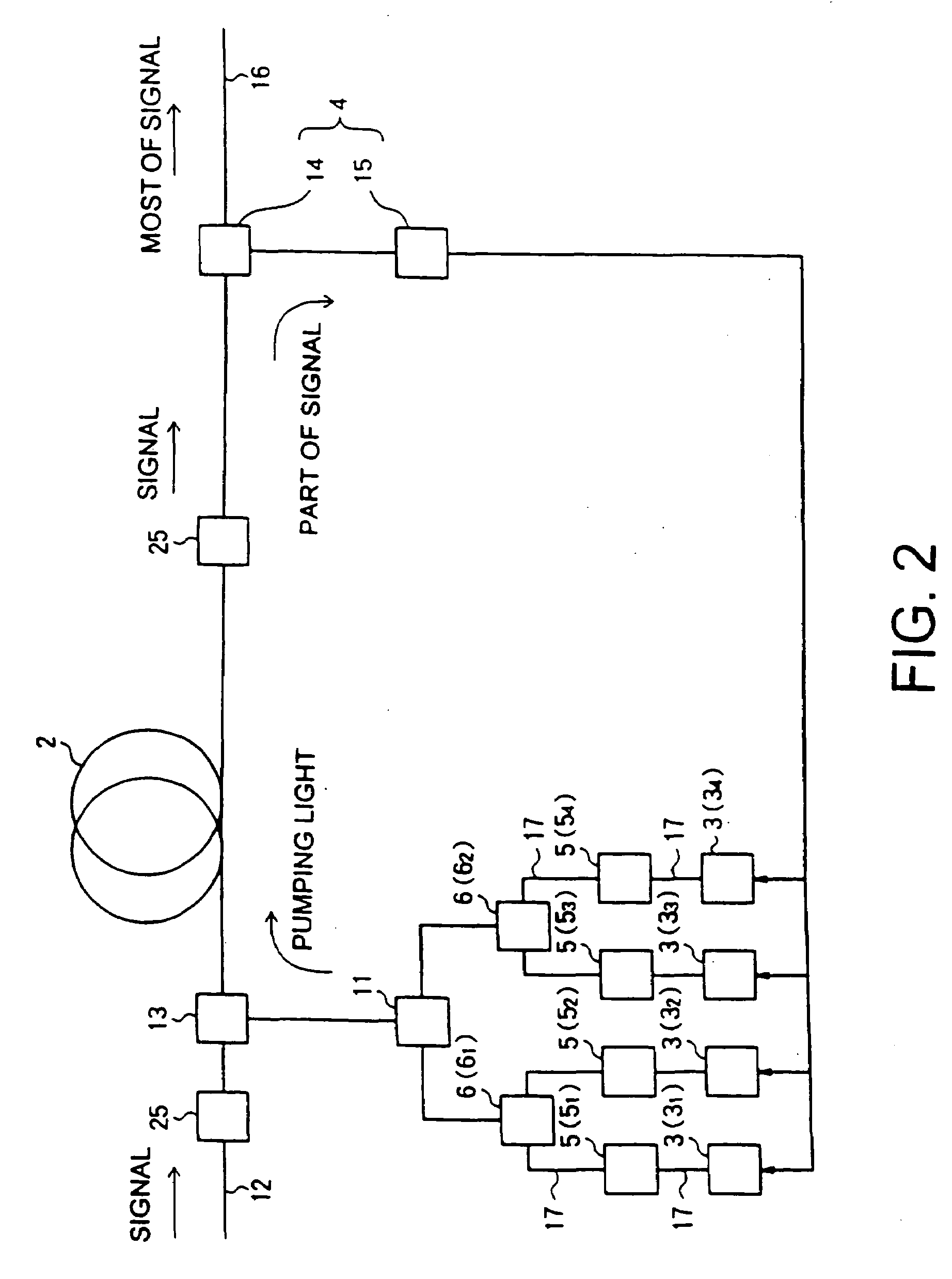
[0144]In an optical repeater according to a sixth embodiment of the present invention, a dispersion compensating fiber is used as the amplifier fiber 2 of the Raman amplifier shown in FIG. 1, 2 or 3 to compensate dispersion of wavelength of the optical fiber transmission line 8, so that the losses in the optical fiber transmission line 8 and the amplifier fiber 2 are compensated partially or totally.

Seventh Embodiment of Optical Repeate...

first embodiment

of Raman Amplifying Method

[0148]An embodiment of a Raman amplifying method according to the present invention will now be fully explained with reference to FIGS. 49 to 52. In this embodiment, a dispersion compensating fiber (DCF) having high non-linearity is used in a Raman amplifying medium 50 shown in FIG. 49 and pumping light generated from an pumping light source 51 is inputted and transmitted to the Raman amplifying medium through a wave combiner 52. In this case, as shown in FIG. 50, as the pumping light source 50, a 4ch-WDMLD unit comprising four pumping light sources (semiconductor lasers), fiber Bragg gratings (FBG), polarization beam combiner (PBC) and a WDM is used. The semiconductor lasers shown in FIG. 50 generate pumping lights having different central wavelengths (more specifically, generate pumping lights having central wavelengths of 1435 nm, 1450 nm, 1465 nm and 1480 nm, respectively). These pumping lights give Raman gain to an optical signal transmitted from the D...


PUM


Abstract

A Raman amplifier according to the present invention comprises a plurality of pumping means using semiconductor lasers of Fabry-Perot, DFB, or DBR type or MOPAs, and pumping lights outputted from the pumping means have different central wavelengths, and interval between the adjacent central wavelength is greater than 6 nm and smaller than 35 nm. An optical repeater according to the present invention comprises the above-mentioned Raman amplifier and adapted to compensate loss in an optical fiber transmission line by the Raman amplifier. In a Raman amplification method according to the present invention, the shorter the central wavelength of the pumping light the higher light power of said pumping light. In the Raman amplifier according to the present invention, when a certain pumping wavelength is defined as a first channel, and second to n-th channels are defined to be arranged with an interval of about 1 THz toward a longer wavelength side, the pumping lights having wavelengths corresponding to the first to n-th channels are multiplexed, and an pumping light having a wavelength spaced apart from the n-th channel by 2 THz or more toward the longer wavelength side is combined with the multiplexed light, thereby forming the pumping light source. The pumping lights having wavelengths corresponding to the channels other than (n-1)-th and (n-2)-th channels may be multiplexed, thereby forming the pumping light source. The pumping lights having wavelengths corresponding to the channels other than (n-2)-th and (n-3)-th channels may be multiplexed, thereby forming the pumping light source.

Description

CROSS REFERENCE TO RELATED APPLICATIONS[0001]This application is a divisional of application Ser. No. 10 / 120,173, filed Apr. 11, 2002 now U.S. Pat. No. 6,775,057; which is a continuation of application Ser. No. 09 / 886,212 filed Jun. 22, 2001, now U.S. Pat. No. 6,654,162; which is a continuation of application Ser. No. 09 / 527,748 filed Mar. 17, 2000, now U.S. Pat. No. 6,292,288; which is a Continuation-in-Part of PCT / JP99 / 03944 filed Jul. 23, 1999.BACKGROUND OF THE INVENTION[0002]1. Field of the Invention[0003]The present invention relates to a Raman amplifier capable of being used for amplification of optical signal in various optical communication systems, and optical repeater and Raman amplification method using such a Raman amplifier, and more particularly, it relates to Raman amplifier, optical repeater and Raman amplification method suitable for amplification of wavelength division multiplexing signals.[0004]2. Related Background Art[0005]Almost all of optical amplifiers used w...

Claims


Application Information

Patent Timeline
Patent Type & Authority Patents(United States)
IPC IPC(8): H04B10/13H04B10/17H01S3/067H01S3/094H01S3/23H01S3/30H04B10/291
CPCH01S3/06754H01S3/094096H01S3/0912H01S3/302H04B10/2916H01S3/06758H01S3/094011H01S3/094015H01S3/10007H01S3/2375H01S3/2383H01S2301/04H01S3/10015H01S3/13013
Inventor AKASAKA, YOUICHIEMORI, YOSHIHIRONAMIKI, SHU
Owner FURUKAWA ELECTRIC CO LTD
Learn More