Method of finishing cutting elements

a cutting element and cutting edge technology, applied in the field of earth-moving bits, can solve the problems of drill bit failure, drill bit wear or breakage, drill bit failure, etc., and achieve the effect of increasing the performance of the drill bit inser

Active Publication Date: 2009-06-23
SMITH INT INC
View PDF14 Cites 11 Cited by
  • Summary
  • Abstract
  • Description
  • Claims
  • Application Information

AI Technical Summary

Benefits of technology

[0008]According to another method of the present invention, the performance of drill bit inserts is increased by accelerating a plurality of inserts in a high-energy finishing machine. The acceleration results in a generally toroidal interaction between the inserts and at least one of the group comprising media, parts, detergents, and solution.

Problems solved by technology

This process, known as a “trip” of the drill string, requires considerable time, effort and expense.
One such cause of drill bit failure is worn or broken cutting inserts.
Cutting inserts may fail by either becoming excessively worn, so that the formation is no longer effectively drilled, or by breaking off, wherein the pieces of broken insert contact the roller cone, potentially leading to roller cone failure.
Whether becoming excessively worn, or breaking off, insert failure can be attributed to either surface or internal flaws of the insert.
Because repairing broken inserts and roller cones is costly and time consuming, significant modifications have been made to the design and manufacturing processes of inserts.

Method used


Image

  • Method of finishing cutting elements
  • Method of finishing cutting elements
  • Method of finishing cutting elements

Examples


Embodiment Construction

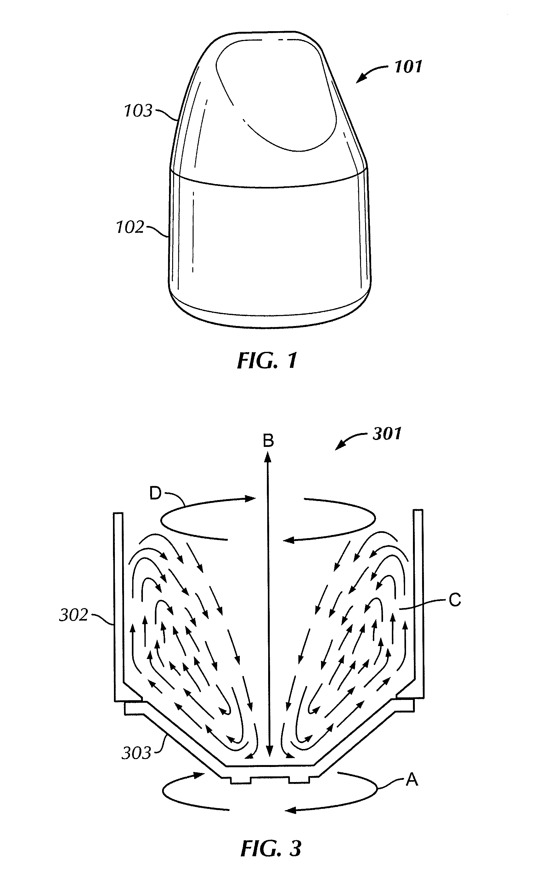
[0016]Referring initially to FIG. 1, a drill bit cutting insert 101 for use in a roller cone drill bit is shown. Inserts 101 are generally formed with at least two areas, a base 102, configured to be press-fit into the roller cone of a drill bit, and a cutting surface 103, designed to contact a formation during drilling. While cutting surface 103 is illustrated in the shape of a chisel, it should be understood that cutting surfaces of different designs known to those skilled in the art, for example, conical and asymmetric inserts, will also benefit from the present invention.

[0017]Still referring to FIG. 1, inserts 101 are typically a composite material made from an abrasion resistant material, for example, tungsten carbide, titanium carbide or tantalum carbide, and a binder, such as cobalt or nickel iron. However, it should be understood that any material benefiting from a high-energy finishing process can be used for inserts 101. For example, fixed drill bits with polycrystalline ...


PUM

PropertyMeasurementUnit
abrasion resistantaaaaaaaaaa
speedaaaaaaaaaa
residual compressive stressesaaaaaaaaaa

Abstract

A method for manufacturing drill bit inserts in which the inserts are finished in a centrifugal disc finishing machine. The centrifugal disc finishing machine comprises a configured surface rotating relative to a stationary receptacle, and the inserts may be finished with a mass of materials comprising at least one of a group of media, parts, detergent, and solution. Also, a method of increasing drill bit insert performance comprising accelerating a plurality of inserts in a high-energy finishing machine, wherein the acceleration results in a generally toroidal interaction between the inserts and at least one of the group comprising media, parts, detergent, and solution.

Description

FIELD OF THE INVENTION[0001]The invention relates generally to earth-boring bits used to drill a borehole for the ultimate recovery of oil, gas, or minerals. More particularly, the invention relates to improving the cutting inserts used in roller cone rock bits.BACKGROUND OF THE INVENTION[0002]An earth-boring drill bit is typically configured on the lower end of a drill string and is rotated by rotating the drill string at the surface or by actuation of downhole motors or turbines, or by both methods. With weight applied to the drill string, the rotating drill bit engages the formation and proceeds to form a borehole along a predetermined path toward a target zone.[0003]A typical earth-boring bit includes one or more rotatable cutters that perform their cutting function due to the rolling movement of the cutters acting against the formation material. The cutters roll and slide upon the bottom of the borehole as the bit is rotated, the cutters thereby engaging and disengaging the for...

Claims


Application Information

Patent Timeline
Patent Type & Authority Patents(United States)
IPC IPC(8): B24B31/108B21K5/06E21B10/46
CPCB24B31/104
Inventor LIANG, DAH-BENVISWANADHAM, RAMAMURTHY K.
Owner SMITH INT INC
Why Eureka
Try Eureka