
Application specific distributed test engine architecture system and method

a distributed test engine and architecture technology, applied in the direction of pulse technique, instruments, computation using denominational number representation, etc., can solve the problems of inefficiency of approach, inconvenient testing, and large complexity of conventional testing, so as to optimize the testing channel and system utilization, the effect of high test throughpu

Inactive Publication Date: 2009-06-23
POCHOWSKI ROBERT
View PDF19 Cites 10 Cited by
  • Summary
  • Abstract
  • Description
  • Claims
  • Application Information

AI Technical Summary

Benefits of technology

This approach significantly increases test throughput, simplifies test programs, and enhances system flexibility and longevity by allowing for reconfiguration and optimization of test resources, thereby reducing testing costs and enabling the testing of more complex devices on existing systems.

Problems solved by technology

The complexity of conventional testing varies widely, as does the cost, from large scale automated test equipment to testing using simple test vectors.
There are various problems with the shared resource approach.
First, this approach becomes inefficient when the DUTs require special testing, e.g., redundancy, programmability, etc.
Higher parallel testing is even less efficient.
Much of this introduced inefficiency is due to the sharing of the single stimulus / response system and the sharing of a single control unit.
Second, this architecture often results in very complicated test programs since the program must be written to insure test integrity under all perturbations of pass / fail conditions of each device.
Third, there can be electrical interactions between the DUTs that negatively affect test performance and integrity.

Method used


Image

  • Application specific distributed test engine architecture system and method
  • Application specific distributed test engine architecture system and method
  • Application specific distributed test engine architecture system and method

Examples


Embodiment Construction

[0035]A preferred embodiment of the present invention is now described with reference to the figures where like reference numbers indicate identical or functionally similar elements. Also in the figures, the left most digit(s) of each reference number corresponds to the figure in which the reference number is first used.

[0036]Reference in the specification to “one embodiment” or to “an embodiment” means that a particular feature, structure, or characteristic described in connection with the embodiments is included in at least one embodiment of the invention. The appearances of the phrase “in one embodiment” in various places in the specification are not necessarily all referring to the same embodiment.

[0037]Some portions of the detailed description that follows are presented in terms of algorithms and symbolic representations of operations on data bits within a computer memory. These algorithmic descriptions and representations are the means used by those skilled in the data process...


PUM


Abstract

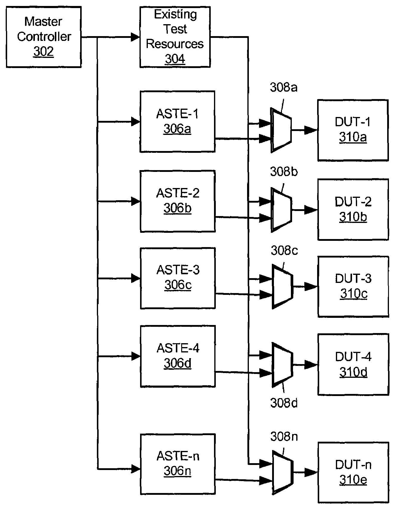
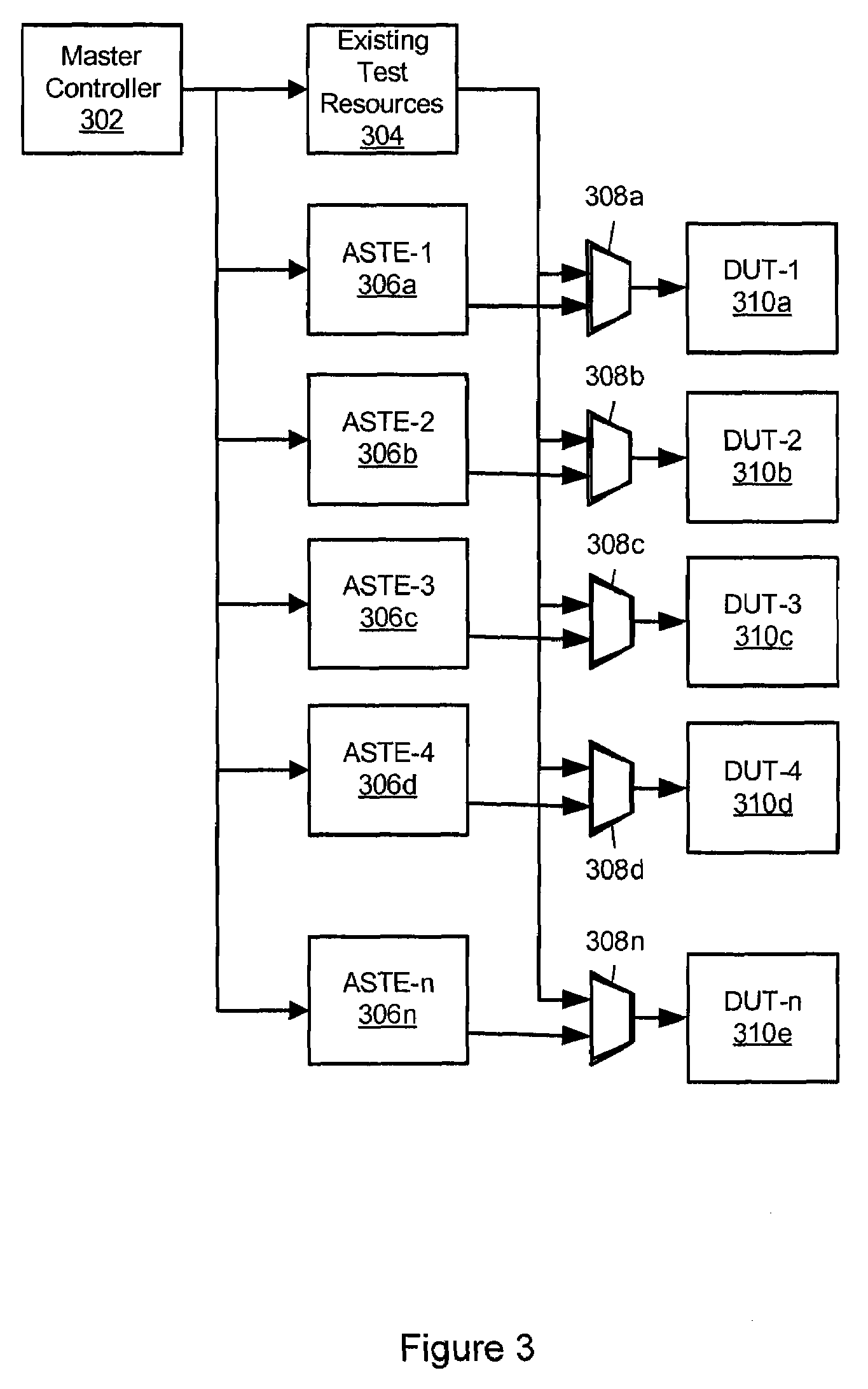
An Application Specific Distributed Test Engine (ASDTE) that provides an optimized set of test resources for a given application. The test engine resources, configuration, functionality, and even the number of test engines can be changed as different devices are tested, or as different test methodologies are used with the system. This can be done by including the test engine configuration as a part of the application files that are loaded during the system set-up. This approach differs from conventional testing systems which limit testing to a fixed, limited, or standard stimulus / response engine configuration intended to test a variety of devices. Some of the benefits of the Application Specific Distributed Test Engine Architecture include: (1) a very high test throughput, (2) the ability to adapt system functionality and capabilities to meet different and new, unforeseen device test requirements on a lot-by-lot basis on a production test floor, and (3) the ability to change the number of test engines to optimize tester channels and system utilization.

Description

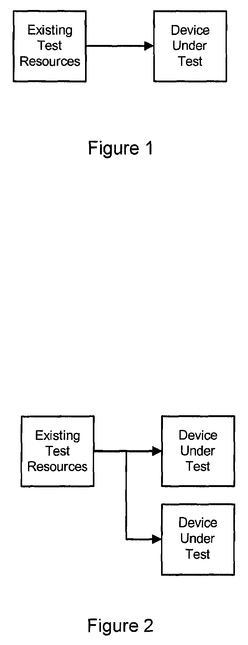
RELATED APPLICATIONS[0001]This application claims priority from U.S. provisional application No. 60 / 787,769 filed on Mar. 31, 2006 which is incorporated by reference herein in its entirety.FIELD OF THE INVENTION[0002]The application is in the field of computer test equipment and more particularly to distributed computer test equipment.BACKGROUND OF THE INVENTION[0003]The ability to efficiently and thoroughly test integrated circuits is a goal for manufacturers and purchasers. The complexity of conventional testing varies widely, as does the cost, from large scale automated test equipment to testing using simple test vectors. What such integrated circuit testing systems have in common is that existing test resources are connected to a Device Under Test (DUT) as shown in FIG. 1. This configuration provides dedicated tester resources to the DUT. These resources can include a control unit, a stimulus / response system and other support functions.[0004]Semiconductor manufacturers have trie...

Claims


Application Information

Patent Timeline
Patent Type & Authority Patents(United States)
IPC IPC(8): G11C29/00G01M19/00G01R13/00G01R31/02G01R31/26G06F7/38H01L25/00H03K19/00H03K19/173G01M99/00
CPCG06F11/263
Inventor POCHOWSKI, ROBERT
Owner POCHOWSKI ROBERT
Learn More