Liquid infusion apparatus

a liquid infusion apparatus and liquid technology, applied in the direction of positive displacement liquid engine, motor/generator/converter stopper, etc., can solve the problem of not having a fully safe operation of the iv controller, the delivery rate and pressure of fluids are not always accurate, and the iv controller is not widely available. problems such as the inability to accurately control the pumping, the effect of reducing the rf emission and reducing the magnetic material

Inactive Publication Date: 2009-06-30
IRADIMED CORP
View PDF56 Cites 101 Cited by
  • Summary
  • Abstract
  • Description
  • Claims
  • Application Information

AI Technical Summary

Benefits of technology

[0015]In accordance with the illustrated embodiment of the present invention a safe and effective infusion device for use within the MRI scan room achieves reduction of magnetic material and accurate pumping control as well as reduction of RF emissions. In one embodiment, the infusion device includes an ultrasonic motor that eliminates magnetic materials and that does not produce any detrimental magnetic fields and that is not affected by external magnetic fields. The ultrasonic (U / S) motor drives a peristaltic or other suitable fluid pumping mechanism, and is driven by a multiphasic electronic signal specifically designed to produce very little RF harmonic noise in the spectral range of about 6 or 8 MHz to about 130 MHz in which MRI receivers are most sensitive. The drive power for the U / S motor is generated via circuitry which produces multiphasic drive signals of at least sine and cosine wareforms at related ultrasonic frequencies. These drive signals are produced as a sinusoidal wave to reduce high frequency harmonic components which may disturb the MRI's RF-sensitive responsiveness. One scheme for producing these multiphasic signals uses coreless or “Air Core” transformers constructed with inherent leakage inductance that interacts with the complex impedance of the U / S motor to convert lower voltage square wave signals at the primary winding into sinusoidal high voltage signals at the secondary windings suitable for powering the U / S motor and producing little harmonic RF interference. Alternatively, D.C. voltages of opposite polarities can be alternately switched to supply alternating voltages. The switched signals can be filtered into sinusoidal signals and applied to the inputs of high voltage linear amplifiers that are set for such gain as needed to produce resultant outputs of sufficient voltage and sinusoidal shape to drive the U / S motor.
[0016]Control electronics receive commands through an input keypad for setting prescribed fluid flow rates to be delivered, and such inputs are translated into signals to control the U / S motor and pumping mechanism. Various safety devices feed back operational information to the control electronics, including detection of motor speed and motion of pump elements, air bubbles in the fluid path, drip rate, high pressure, low fluid, low / no flow, overtime, and the like. The present infusion device includes battery power for portability, and is housed in one RF-shielded, non-magnetic housing for convenient location anywhere within the MRI scan room without introducing image degrading RF interference or producing distortions of the homogeneous magnetic field, and without being affected by the strong magnetic fields or RF energy produced by the MRI system. Such unrestricted placement of the device is of great importance to the safety and convenience of the attending MRI staff and imaging patient. Further, in the case of a linear peristaltic pump mechanism, the particular position of pump elements, along with the speed of motion of these elements, must be known to the controller. The degree to which the controller may modulate speed and control exact positions of the pump elements directly affects the resolution and accuracy of the fluid delivery system. To provide a high degree of speed and position accuracy, an optical encoder (801, 802) is installed along the main pump shaft. The encoder disk (802) has many small graticule marks about the circumference, and a single index mark. The optical sensor (801) detects the marks and produces output signals indicative of both the index and individual graticule marks. The index occurs only once each 360 degrees of rotation to facilitate the controller sensing an index to know the position of the pumping elements. The rate at which the graticule marks are sensed indicates the speed of the pump shaft as well as its fine position relative to the index mark. The controller responds to the optical encoder to modulate the speed of motion of the pump elements at specific positions of the pump shaft in order to reduce inherent non-linearities in fluid delivery of the linear-type peristaltic pump. In this way, highly accurate and linear fluid flow may be achieved.
[0017]In an additional embodiment, a method is employed to substitute an MRI-compatible pumping device for a prior-connected, non-MRI-compatible pumping device while preserving the patient's connection to a prior-connected primary intravenous (IV) infusion set. The patient is commonly connected to a primary IV set through a primary, non-MRI-compatible pump. Upon arrival at the MRI suite, a secondary, MRI-compatible pump attached to a secondary IV set connects to the primary IV set to continue actively-pumped IV fluid delivery. The primary pump is disengaged from the patient's installed primary IV set, and a flow preventer (to shut off flow) that is standard on most IV sets is activated to inhibit liquid flow through a segment of the primary IV set. The fluid-receiving or proximal end of the secondary IV set is connected to the upstream end of the primary IV set near the source of the IV fluid. The upstream connection may be conveniently formed by puncturing a conventional “Y” connector on the primary IV set with a hollow needle on the secondary IV set, or via a luer-type “Y” site connector. Air is flushed from the secondary IV set by flowing fluid from the upstream connection, and the fluid-delivery or distal end of the secondary IV set is then connected in similar manner at a downstream connection in the primary IV set. Pumping of the liquid may then be resumed using the MRI-compatible pump operating on the secondary IV set without having dislodged the intra-vascular needle or actually opening the primary IV circuit. The patient and MRI-compatible pump may then be moved close to the MRI scanner while maintaining the controlled IV therapy. The secondary IV set so employed may simply be disconnected and discarded after the MRI procedure, again without opening the original primary IV circuit, and the original primary IV set may be reinstalled into the original, non-MRI-compatible pump while preserving the patient's connection to the primary IV set. By not opening the fluid circuit of the primary set, minimal risk to the patient and sterile IV path are achieved as well as reducing medical waste and cost of replacing the primary IV set after the MRI procedure.
[0018]To facilitate rapid transitions between primary and secondary pumps and infusion sets, one embodiment of the present invention includes an infusion device that receives a liquid conduit for delivering liquid to a patient at volumetric rates that are controllable by the device. Peristaltic pumping of liquid through the conduit installed within the device is enabled only upon proper registration of a flow valve within a receptacle of the device for actuation upon closing of a safety door. Flow of liquid through the conduit is inhibited upon opening the safety door, and various sensors are incorporated into the device along the path of the conduit to detect inflow and outflow liquid pressures, available liquid supply, air bubbles in the conduit, and the like.

Problems solved by technology

Conventional gravity IV solution delivery via commonly-available IV administration sets is typically not sufficiently accurate for the delivery of many types of fluids and drugs.
However, there currently exists no IV controller capable of completely safe operation within a MRI suite wherein a considerable need exists for the controlled delivery of medicinal liquids.
Certain physical limitations regarding the delivery rate and pressure are elemental in IV liquid-infusion control.
The high magnetic field surrounding MRI systems can negatively affect the operation of various devices (including conventional IV control devices), especially those devices that are constructed with magnetic materials, and can seriously jeopardize a patient's safety as a result of devices utilizing magnetic materials that can be attracted at high velocity into the magnetic field of the MRI system where patient or attendant personnel are located.
Such control unit may emit spurious radio frequency signals as a result of poor electrical design or insufficient shielding and are therefore commonly installed outside an MRI environment and outside the shielding therefor.
Electrically passive metallic items such as oxygen bottles or ‘crash carts’ present safety hazards to the patient due to their potential to be strongly attracted by the magnetic field of the scanner.
Such items can be ‘pulled’ into the imaging volume where the patient is located, creating potential for serious injury or death.
Thus, devices formed of magnetic material that are positioned within the magnetic field of the scanner can introduce distortions into this homogeneous field and the resultant images.
However, such devices with some ferrous mass, though inhibited from being pulled into the magnetic field, may nevertheless introduce inhomogeneity in the magnetic field.
And, the possibility of field distortion is proportionally increased as devices with metallic materials are positioned closer to the imaging volume, with the most critical position being near the center of the imaging volume, essentially where the patient is positioned.
Such noise can so degrade the signal-to-noise ratio of signals received by the MRI sensor coils and receivers that image resolution is reduced or rendered completely unreadable.
The intense magnetic fields produced by the MRI scanner can cause detrimental effects on the performance of common DC and stepper motors in devices needed within the MRI scanning room, to the point of making their control difficult or causing their complete failure.
The gradient or time-varying magnetic fields can induce changing (AC) currents in motors and associated circuitry which may also cause false motor operation.
Such devices must not emit any significant RF emissions that might adversely affect image acquisition operation from within the MRI scan room and must not interact with the magnetic fields therein either to cause distortion of the field or to be influenced by these fields sufficiently to jeopardize reliable operation of such devices.
Switching a patient's IV set involves a health risk due to sterility concerns and a cost in medical personnel's time.
Additionally, fluid may be wasted from a prescribed volume during the IV-switch procedure.

Method used


Image

  • Liquid infusion apparatus
  • Liquid infusion apparatus
  • Liquid infusion apparatus

Examples


Embodiment Construction

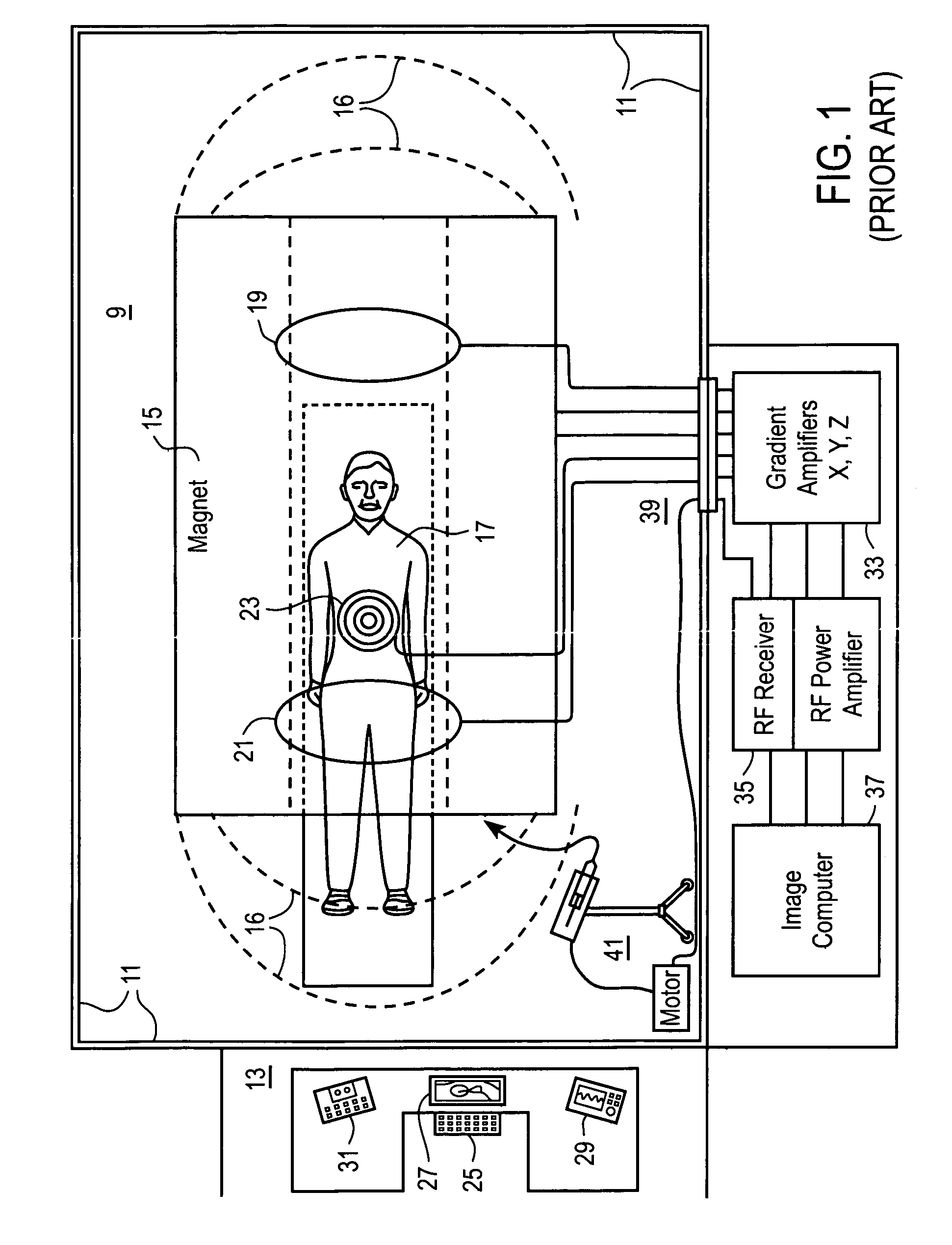
[0039]Pending application Ser. No. 10 / 964,333 entitled “Non-Magnetic Medical Infusion Device”, filed on Oct. 12, 2004 by R. Susi, and issued U.S. Pat. No. 7,267,661 entitled “Non-Magnetic Medical Infusion Device” filed on Jun. 17, 2002 by R. Susi are incorporated herein in their entireties by this reference thereto. Referring now to the plan view in FIG. 1 of an MRI system, the scanning room 9 is disposed within shielding boundary walls 11, with a control room 13 for operators or attendant personnel positioned outside the boundaries of the scanning room 9. The scanning room 9 includes the image acquisition equipment including a source 15 of intense magnetic field 16 that emanates from the source in substantially homogenous array throughout the adjacent space and around a patient 17. Various components of the system for performing the image acquisition operations, including gradient 19 and sensor 21 and RF coils 23 are disposed about the patient 17 for stimulating the nuclei ‘echos’ ...


PUM


Abstract

Liquid infusion apparatus includes non-magnetic materials in a pumping structure and ultrasonic drive motor therefor, and in a controller that supplies drive signals to the motor to facilitate convenient operation in intense magnetic fields without distorting the magnetic fields and without radiating objectionable radio-frequency interference. A non-MRI-compatible liquid infusion apparatus is temporarily replaced with MRI-compatible, non-magnetic liquid infusion apparatus without disconnecting a patient from an installed intravenous infusion set to continue infusing liquid within the MRI environment. The pumping apparatus operates on a segment of a liquid conduit that is mounted in tension between a linear peristaltic pump and platen, with associated safety interlocks to assure proper operation of infusing liquid into a patient compatibly with conditions in an MRI environment. Drive circuitry generates low-harmonic signals for operating the ultrasonic motor at variable speeds to compensate for flow rate discontinuities through the peristaltic pumping cycles.

Description

FIELD OF THE INVENTION[0001]This invention relates to apparatus for refusing liquid into a patient, and more particularly to such apparatus suitable for operation in a magnetic resonance image (MRI) environment of high magnetic fields and required low radiofrequency interference.BACKGROUND OF THE INVENTION[0002]It is desirable to carefully control the intravenous (IV) administration of liquids to a patient. Conventional gravity IV solution delivery via commonly-available IV administration sets is typically not sufficiently accurate for the delivery of many types of fluids and drugs. Various positive displacement pumping devices have been developed for carefully controlling such IV administration. Some types of IV pumps control flow within a standard IV administration set via peristaltic (either linear or rotary) pumping schemes directly on the tubing of a conventional IV infusion set. Other types may incorporate a proprietary volumetric cassette, and still other types utilize a syri...

Claims


Application Information

Patent Timeline
Patent Type & Authority Patents(United States)
IPC IPC(8): A61M1/00H02K33/00
CPCF04B43/082A61M5/14228A61M5/172A61M5/142A61M39/26A61M2205/14A61M5/1413
Inventor SUSI, ROGER E.
Owner IRADIMED CORP
Why Eureka
Try Eureka