
Multi-material stereolithography

a stereolithography and multi-material technology, applied in the field of rapid prototyping technology, can solve the problems of insufficient oxygen and nutrients to sustain cell viability, implantable multi-material hydrogel constructs are not currently suited for single-material sl machines known in the art, and achieve the effects of improving sl functionality, eliminating material contamination, and maintaining a sterile and non-contaminating building environmen

Active Publication Date: 2009-07-07
BOARD OF RGT THE UNIV OF TEXAS SYST
View PDF50 Cites 179 Cited by
  • Summary
  • Abstract
  • Description
  • Claims
  • Application Information

AI Technical Summary

Problems solved by technology

One of the most challenging problems in TE involves promoting cell in-growth and perfusion to seeded cells in implanted scaffolds.
The diffusion of oxygen and nutrients is not sufficient to sustain cell viability beyond distances of approximately 100 microns in the body.
Implantable multi-material hydrogel constructs, however, are not currently suited for single material SL machines known in the art.

Method used


Image

  • Multi-material stereolithography
  • Multi-material stereolithography
  • Multi-material stereolithography

Examples


Embodiment Construction

[0041]While the making and using of various embodiments of the present invention are discussed in detail below, it should be appreciated that the present invention provides many applicable inventive concepts that can be embodied in a wide variety of specific contexts. The specific embodiments discussed herein are merely illustrative of specific ways to make and use the invention and do not delimit the scope of the invention.

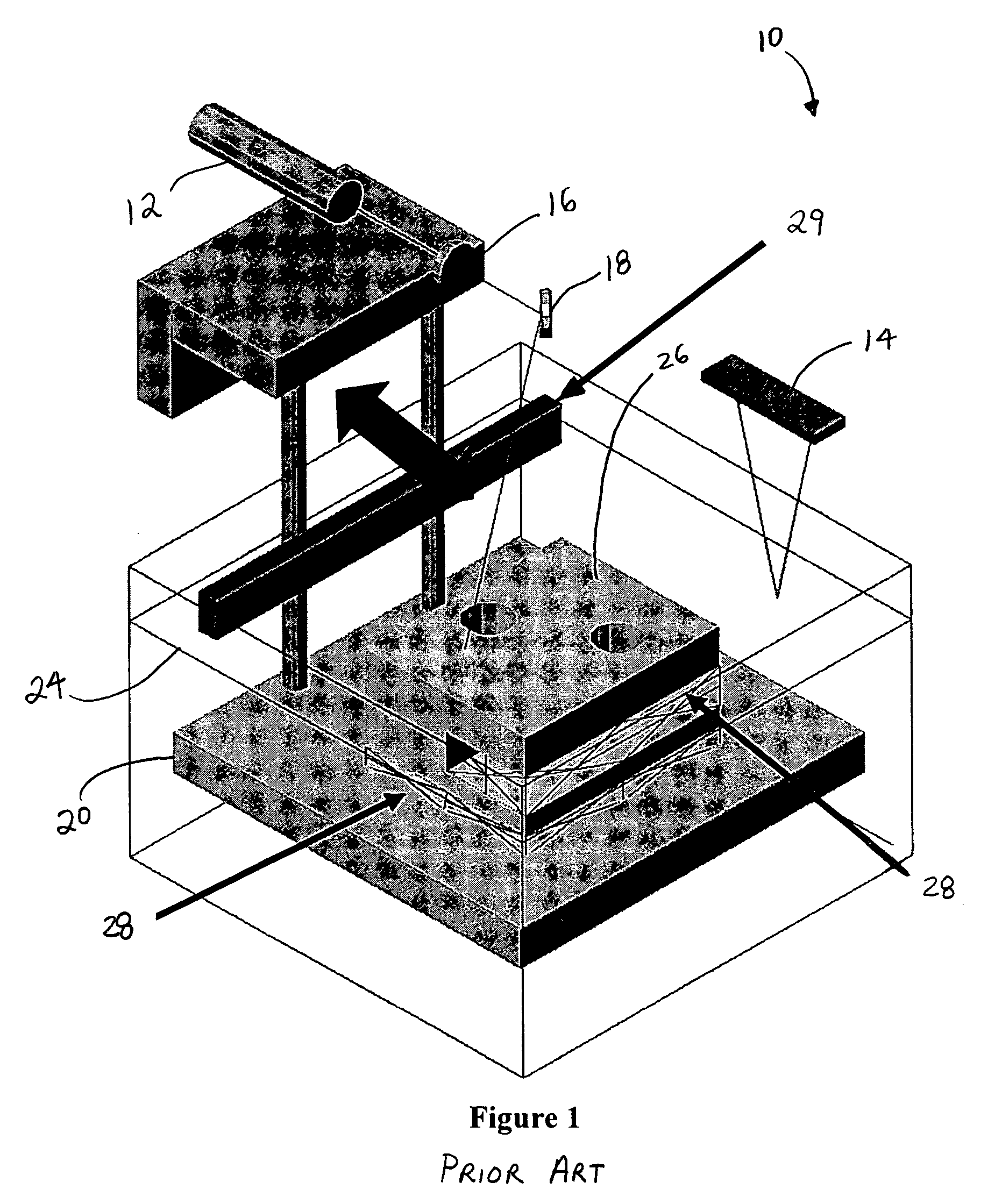
[0042]A typical prior art SL machine 10, as illustrated in FIG. 1, generally includes a UV laser beam 12, a liquid level sensing system 14, optics 16 and controllable mirror system 18, a vertically movable platform 20 and a resin retaining receptacle or vat 22. The vat 22 houses a liquid photocurable polymer resin 24 and, generally, the SL machine 10 rasters a UV laser beam 12 across the resin through a series of optics 16 and a controllable mirror system 18. In most designs, the subject three-dimensional (3D) part 26 is usually first attached to the platform 20 ...


PUM

PropertyMeasurementUnit
distancesaaaaaaaaaa
thicknessaaaaaaaaaa
thicknessaaaaaaaaaa

Abstract

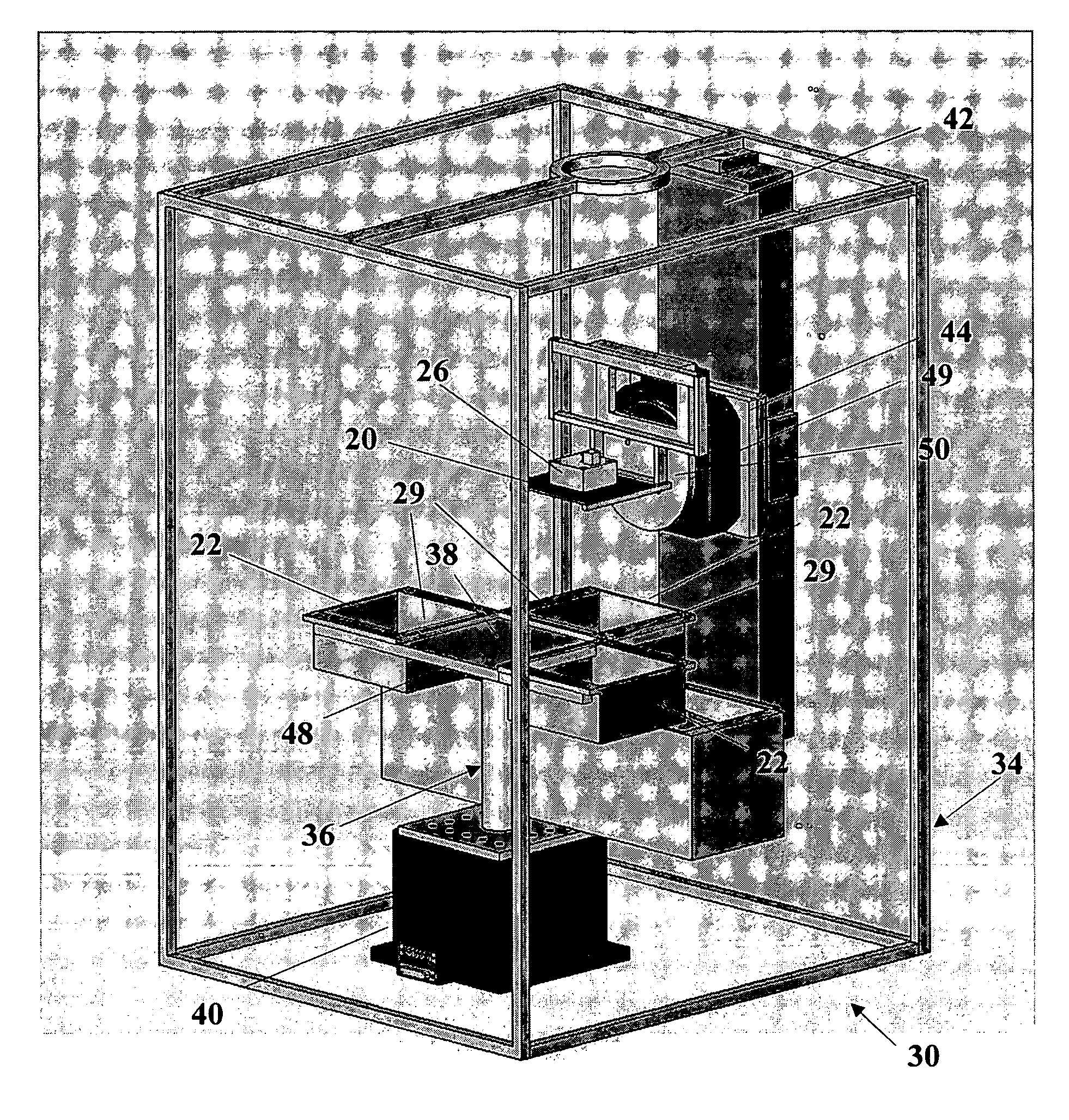
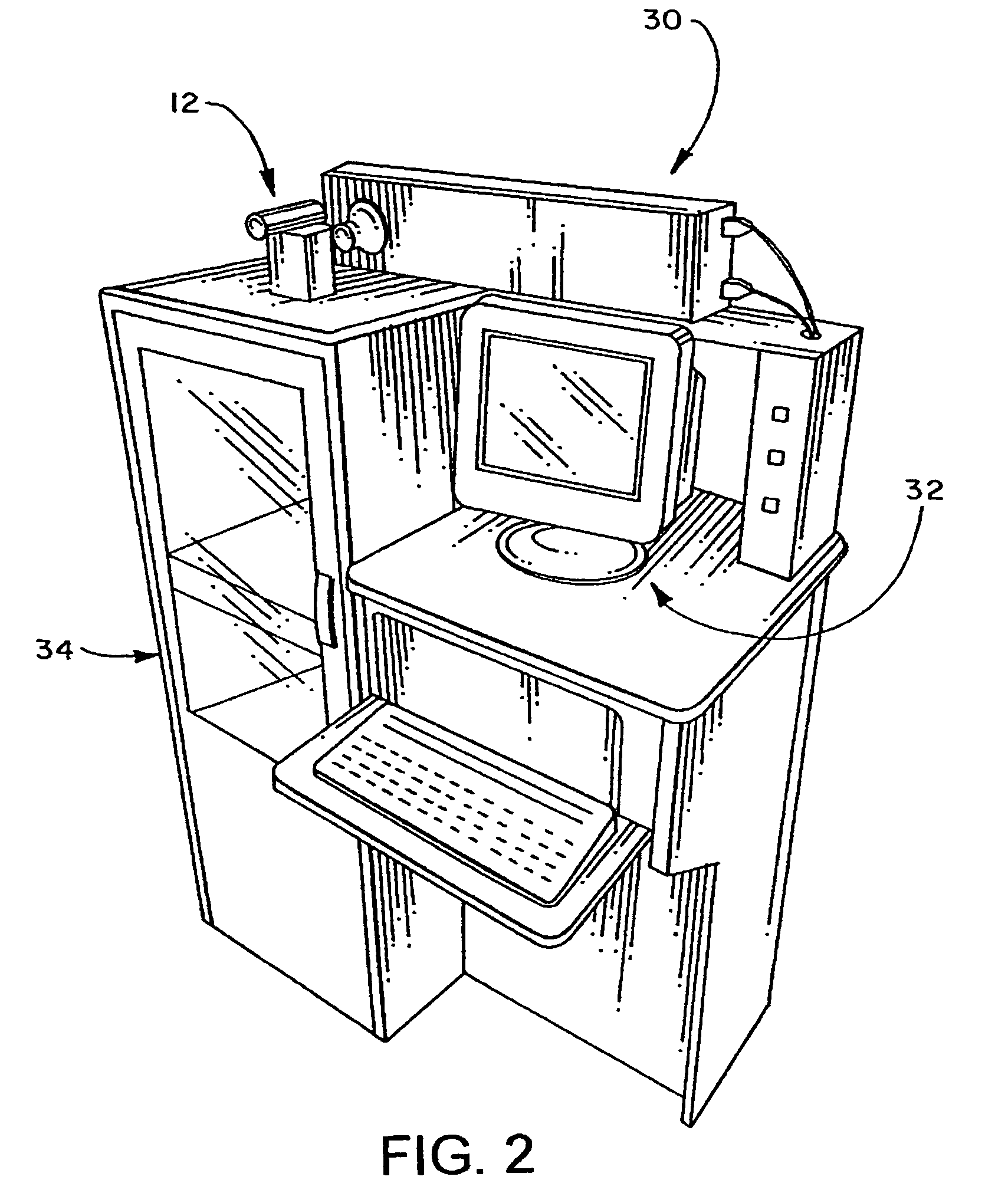
Methods and systems of stereolithography for building cost-efficient and time-saving multi-material, multi-functional and multi-colored prototypes, models and devices configured for intermediate washing and curing / drying is disclosed including: laser(s), liquid and / or platform level sensing system(s), controllable optical system(s), moveable platform(s), elevator platform(s), recoating system(s) and at least one polymer retaining receptacle. Multiple polymer retaining receptacles may be arranged in a moveable apparatus, wherein each receptacle is adapted to actively / passively maintain a uniform, desired level of polymer by including a recoating device and a material fill / remove system. The platform is movably accessible to the polymer retaining receptacle(s), elevator mechanism(s) and washing and curing / drying area(s) which may be housed in a shielded enclosure(s). The elevator mechanism is configured to vertically traverse and rotate the platform, thus providing angled building, washing and curing / drying capabilities. A horizontal traversing mechanism may be included to facilitate manufacturing between components of SL cabinet(s) and / or alternative manufacturing technologies.

Description

BACKGROUND[0001]The present invention relates to the general field of rapid prototyping technology, and in particular, to stereolithography methods and systems.[0002]Rapid prototyping (RP) technologies, also known as Solid Freeform Fabrication (SFF), layered manufacturing and other similar technologies enable the manufacture of complex three-dimensional (3D) parts. RP technologies, in particular, generally construct parts by building one layer at a time. RP technologies are commonly used to build parts and prototypes for use in, for example, the toy, automotive, aircraft and medical industries. Oftentimes prototypes made by RP technologies aid in research and development and provide a low cost alternative to traditional prototyping. In a few cases, RP technologies have been used in medical applications such as those associated with reconstructive surgery and tissue engineering (TE).[0003]Stereolithography (SL) is one of the most widely used RP technologies known in the art. The reso...

Claims


Application Information

Patent Timeline
Patent Type & Authority Patents(United States)
IPC IPC(8): B28B1/16B29C35/08
CPCB29C67/0066B29C67/0062B29C64/124B29C64/135B33Y30/00B33Y70/00B33Y40/00B33Y10/00B33Y40/20
Inventor WICKER, RYANMEDINA, FRANCISCOELKINS, CHRISTOPHER
Owner BOARD OF RGT THE UNIV OF TEXAS SYST
Learn More