Method for operating gas turbine engine systems

a gas turbine engine and combustion system technology, applied in the ignition of turbine/propulsion engines, engine starters, lighting and heating apparatus, etc., can solve the problems of combustion dynamics, combustion design is unable to operate in the low no/sub>combustion mode, and takes a day or longer to achiev

Active Publication Date: 2009-07-28
GE INFRASTRUCTURE TECH INT LLC
View PDF23 Cites 37 Cited by
  • Summary
  • Abstract
  • Description
  • Claims
  • Application Information

AI Technical Summary

Benefits of technology

[0012]In another embodiment, the gas turbine control system continuously receives fuel properties sufficient to calculate fuel MWI and maintains fuel temperature compatible with the improved efficiency of higher inlet fuel temperatures and modulates fuel splits in the fashion indicated in the fourth embodiment.

Problems solved by technology

Such fuel schedule adjustments is called “tuning” and is a process requires technicians to set up special instrumentation and may take a day or longer to accomplish.
Until the fuel gas reaches the required temperature and consequently the required MWI, some combustor designs are unable to operate in the low NOx combustion mode.
Operation outside of the design MWI range can for some of the DLN combustion systems result in combustion dynamics levels (noise due to oscillatory combustion process) that is large enough to shorten the maintenance intervals or even cause hardware damage and forced outages.

Method used


Image

  • Method for operating gas turbine engine systems
  • Method for operating gas turbine engine systems
  • Method for operating gas turbine engine systems

Examples


Embodiment Construction

[0016]While the methods and apparatus are herein described in the context of a gas turbine engine used in an industrial environment, it is contemplated that the method and apparatus described herein may find utility in other combustion turbine systems applications including, but not limited to, turbines installed in aircraft. In addition, the principles and teachings set forth herein are applicable to gas turbine engines using a variety of combustible fuels such as, but not limited to, natural gas, gasoline, kerosene, diesel fuel, and jet fuel. The description hereinbelow is therefore set forth only by way of illustration, rather than limitation.

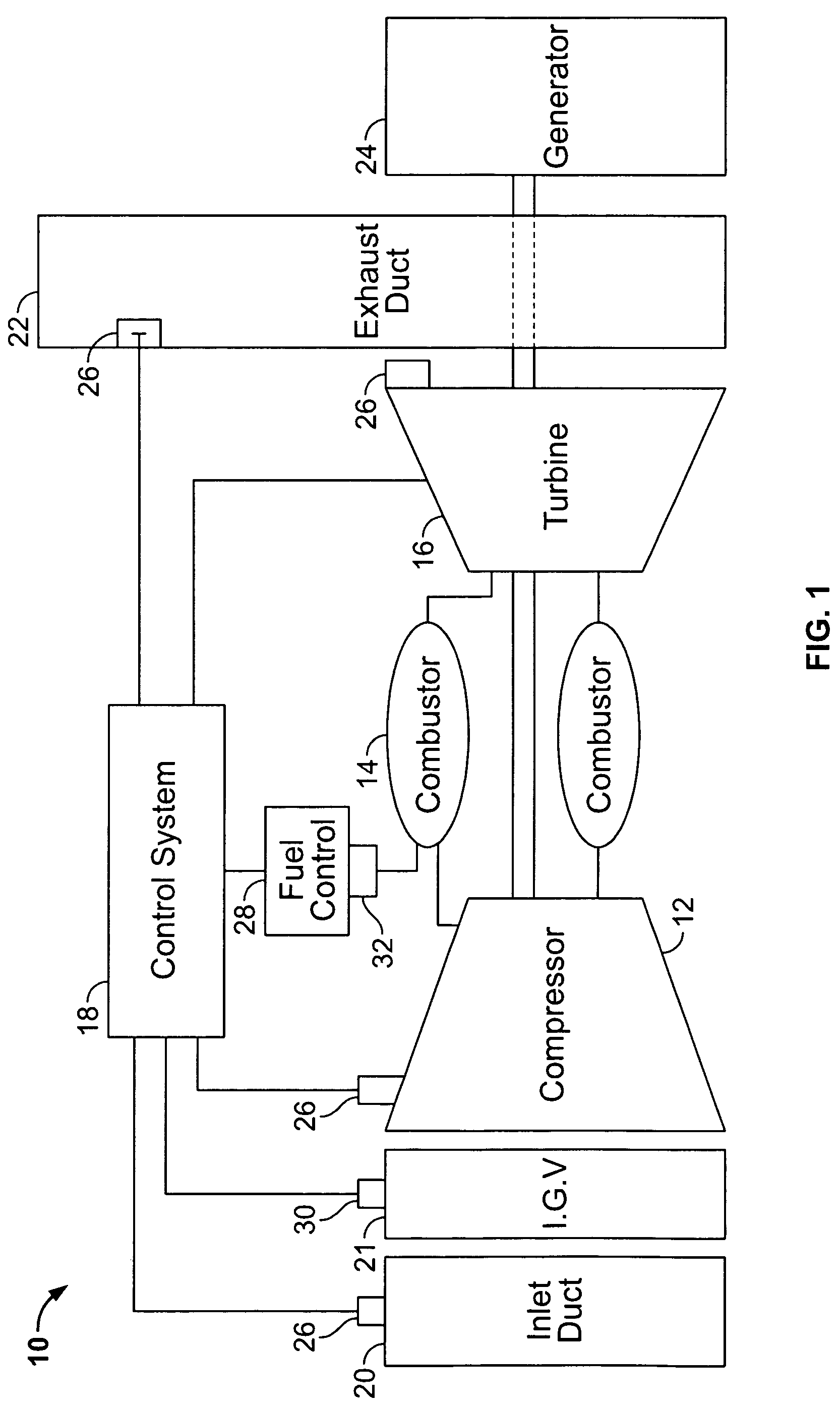
[0017]FIG. 1 is a schematic diagram of a gas turbine engine system 10 including a compressor 12, a combustor 14, a turbine 16 drivingly coupled to compressor 12, the gas turbine engine managed by a combination of operator commands and a control system 18. An inlet system 20 channels ambient air to the compressor inlet guide vanes 21 which by...


PUM


Abstract

Methods and systems for operating a gas turbine engine system include an electrical generator configured to provide electrical energy to a load, a gas turbine engine including at least one combustor that includes a plurality of fuel injection points configured to inject a fuel into the combustor at a plurality of different locations wherein the combustor configured to combust the fuel and the gas turbine engine is rotatably coupled to the generator through a shaft. The gas turbine engine system includes a control system including a plurality of sensors positioned about the gas turbine engine system and configured to measure at least one parameter associated with the sensor, a processor programmed to receive a signal indicative of a heating value of the fuel, and automatically control a fuel split between the fuel injection points on the combustor using the determined heating value.

Description

BACKGROUND OF THE INVENTION[0001]This invention relates generally to gas turbine engine combustion systems, and more particularly, to methods and apparatus for controlling the operation of the combustion systems.[0002]Gas turbine engines typically include a compressor section, a combustor section, and at least one turbine section. The compressor discharge air is channeled into the combustor where fuel is injected, mixed and burned. The combustion gases are then channeled to the turbine which extracts energy from the combustion gases.[0003]Gas turbine engine combustion systems must operate over a wide range of flow, pressure temperature and fuel / air ratio operating conditions. Controlling combustor performance is required to achieve and maintain satisfactory overall gas turbine engine operation and to achieve acceptable emissions levels, the main concern being NOx and CO levels.[0004]One class of gas turbine combustors achieve low NOx emissions levels by employing lean premixed combu...

Claims


Application Information

Patent Timeline
Patent Type & Authority Patents(United States)
IPC IPC(8): F02C3/22F02C9/26
CPCF23N5/003F23R3/00F23N2021/10Y02T50/677F23N2041/20F23N2221/10F23N2241/20Y02T50/60
Inventor STEBER, CHARLES EVANPARISAY, MASSOUDANNIGERI, RAVINDRAZIMINSKY, WILLY STEVEHENDERSON, JOHN STEPHEN
Owner GE INFRASTRUCTURE TECH INT LLC
Why Eureka
Try Eureka