Check patentability & draft patents in minutes with Patsnap Eureka AI!

Ion source and polishing system using the same

a technology of ion source and polishing system, which is applied in the direction of solid cathode, gas-filled discharge tube, ion beam tube, etc., can solve the problems of difficult to accurately control the polishing of such areas, difficult to reach/treat and/or small areas of workpieces, and relatively rough areas of machining

Inactive Publication Date: 2009-07-28
HON HAI PRECISION IND CO LTD
View PDF1 Cites 3 Cited by
  • Summary
  • Abstract
  • Description
  • Claims
  • Application Information

AI Technical Summary

Benefits of technology

Enables precise control of ion beam diameter and surface roughness in the nanometer range, effectively polishing complex surface geometries with improved precision and accuracy, achieving surface roughness control from 0.2 to 1.0 nanometers.

Problems solved by technology

However, in a traditional electrical discharge machining (EDM), the areas of machining become relatively rough, within surface roughness in the micrometer range.
However, many, if not most, workpieces have some areas that are difficult to reach / treat and / or small areas, such as, for example, a narrow area, slot, slope surface, sharp angle surface, concave portion, and / or convex portion.
During polishing, the aforementioned ion source usually has a problem with the difficult and / or small areas, making polishing of such areas difficult to accurately control or at least making adjustment between different areas challenging.
In other words, this ion source has generally not proven suitable for treating surfaces with difficult and / or small areas.

Method used


Image

  • Ion source and polishing system using the same
  • Ion source and polishing system using the same
  • Ion source and polishing system using the same

Examples


Embodiment Construction

[0017]Embodiments of the present ion source and polishing system will now be described in detail below and with reference to the drawings.

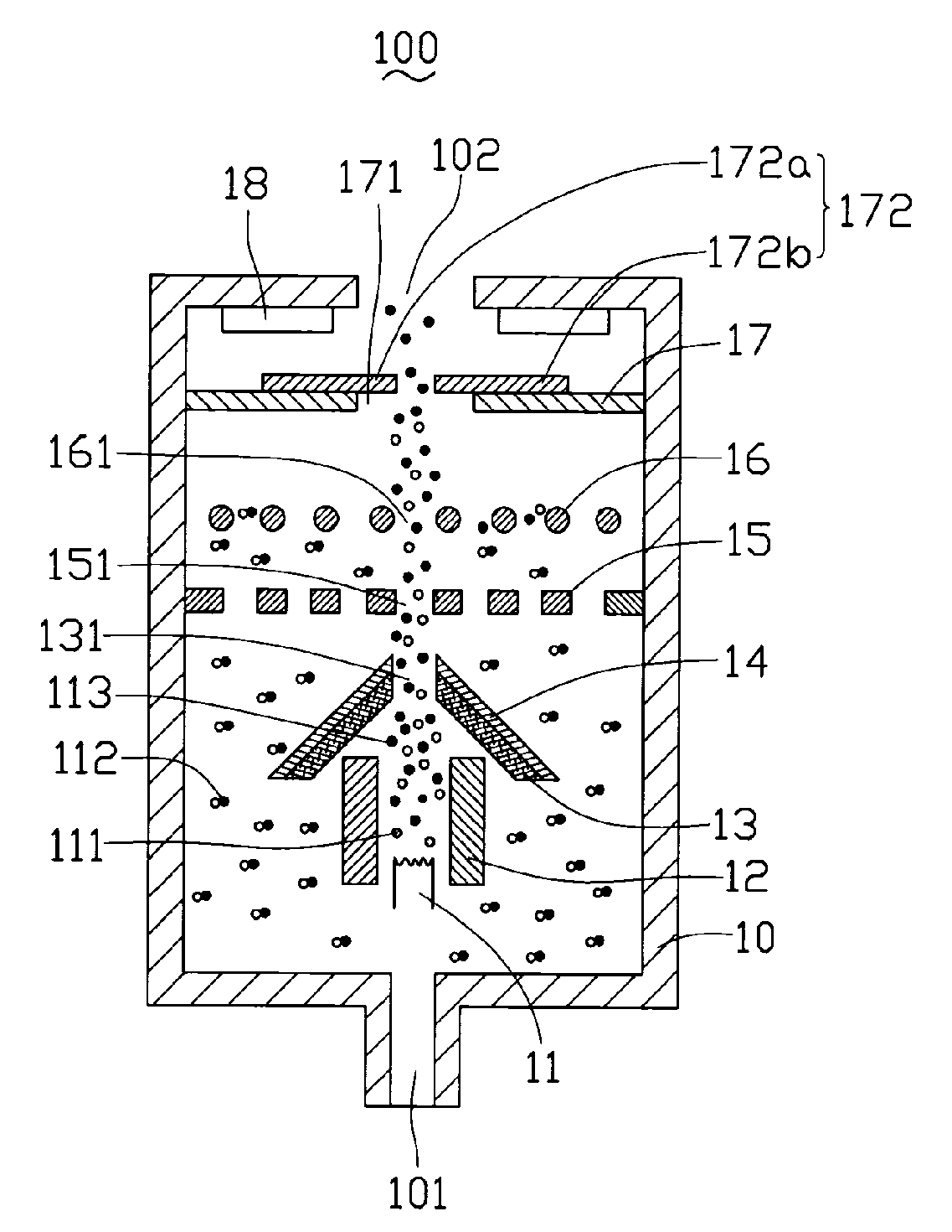
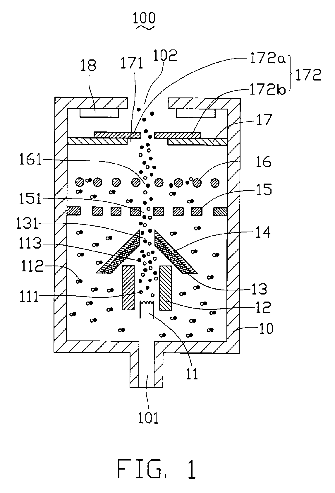
[0018]FIG. 1 illustrates an ion source 100, in accordance with a preferred embodiment. The source 100 includes a discharge chamber 10, an electron emitter 11, a magnetic coil 12, a cathode 13, a screen grid 15, an accelerator grid 16, a screen electrode 17, and a neutralizer 18, advantageously in that general, uninterrupted order. The discharge chamber 10 includes an inlet 101 and an outlet 102 in two opposite walls thereof. The inlet 101 is configured for supplying discharge gas (e.g., Argon) 112 into the discharge chamber 10. The outlet 102, meanwhile, is configured for allowing ion beams to eject / exit therefrom. The electron emitter 11, the magnetic coil 12, the cathode 13, the screen grid 15, the accelerator grid 16, the screen electrode 17, and the neutralizer 18 are separately aligned in the discharge chamber 10, in an ascending order with r...


PUM


Abstract

An ion source and a polishing system using the ion source are disclosed. The ion source includes a discharge chamber, an electron emitter, a cathode, a screen grid, an accelerator grid, and a screen electrode. The discharge chamber is configured for accommodating discharge gas. The electron emitter is disposed in the discharge chamber. The cathode, the screen grid, the accelerator grid, and the accelerator grid are separately aligned in the discharge chamber in an ascending order with respect to the respective distance thereof from the electron emitter. The electron emitter, the cathode, the screen grid, the accelerator grid, and the accelerator grid are powered in order of descending voltages. The screen electrode defines an adjustable orifice to permit adjustment of an ion-beam ejecting area associated with the orifice. The polishing system further employs a movable stage and control and monitor components, in addition to the ion source.

Description

FIELD OF THE INVENTION[0001]The present invention relates to ion sources and, more particularly, to an ion source and a polishing system using the ion source.DESCRIPTION OF RELATED ART[0002]Ion sources are typically devices that ionize gas molecules and then focus, accelerate, and emit them as narrow ion beams. The ion beams can be used for various technical and technological purposes such as cleaning, activation, polishing, thin-film coating, aligning, or etching.[0003]Many ion sources need to emit focused ion beams for some technological purposes, for example, for selectively etching and / or polishing of a small area. With advances in technology, there is increasingly a demand for precision polishing of surfaces for a variety of purposes. For example, highly polished precision surfaces are needed in molds, optical elements (e.g., optical lenses), and in the fabrication of semiconductor elements (e.g., silicon wafers).[0004]A typical focused ion source can be used to alter selected ...

Claims


Application Information

Patent Timeline
Patent Type & Authority Patents(United States)
IPC IPC(8): H05H5/03
CPCH01J27/08H01J37/08H01J37/3053H01J2237/3151H01J2237/061H01J2237/0835H01J2237/30477H01J2237/0455
Inventor CHEN, GA-LANE
Owner HON HAI PRECISION IND CO LTD
Features
  • R&D
  • Intellectual Property
  • Life Sciences
  • Materials
  • Tech Scout
  • Unparalleled Data Quality
  • Higher Quality Content
  • 60% Fewer Hallucinations
Learn More