Amplifier arrangement, polar transmitter having the amplifier arrangement and method for amplifying signals

a technology of amplifier arrangement and amplifier arrangement, which is applied in the field of amplifier arrangement, can solve the problems of data transmission error, illustrated i/q modulator and large power consumption

Active Publication Date: 2009-08-04
APPLE INC
View PDF6 Cites 12 Cited by
  • Summary
  • Abstract
  • Description
  • Claims
  • Application Information

AI Technical Summary

Benefits of technology

[0011]In one embodiment, the amplitude of a carrier signal which has already been phase-modulated is modulated using the amplifier stage. The modulation is advantageously effected by supplying an amplitude-modulated supply potential to the amplifier stage. The power consumption is thus reduced in the amplifier arrangement. The amplitude-modulated supply potential is provided by the DC voltage converter. The term supply potential in at lest one example is understood as meaning the term supply voltage. In other words, modulating the supply potential also modulates the supply voltage. The terms voltage and potential are thus used synonymously in one example. A phase-modulated signal likewise also represents a frequency-modulated signal in one example.
[0017]This has the advantage that a particularly wide dynamic range is available for the amplitude modulation. The signal-to-noise ratio is improved, as regards amplitude modulation, with the aid of voltage signals. The amplifier arrangement specified can thus also be implemented with low supply voltages in a semiconductor body using CMOS technology. A further reduction in size to smaller dimensions in the submicron range is likewise possible.
[0020]One embodiment also provides a correction circuit which is configured to output a correction current to the first connection of the current mirror transistor. This makes it possible, on the one hand, to correct differences in the production process between the current mirror transistor and the amplifier transistors in the amplifier stage and, on the other hand, to also compensate for a DC voltage offset in the amplifier stage.

Problems solved by technology

DC signal components in the supplied signals i(t) and q(t) are likewise converted to the transmission frequency by the mixers and may thus result in errors in the transmission of data.
The illustrated I / Q modulator also consumes a relatively large amount of power on account of the two mixers.

Method used


Image

  • Amplifier arrangement, polar transmitter having the amplifier arrangement and method for amplifying signals
  • Amplifier arrangement, polar transmitter having the amplifier arrangement and method for amplifying signals
  • Amplifier arrangement, polar transmitter having the amplifier arrangement and method for amplifying signals

Examples


Embodiment Construction

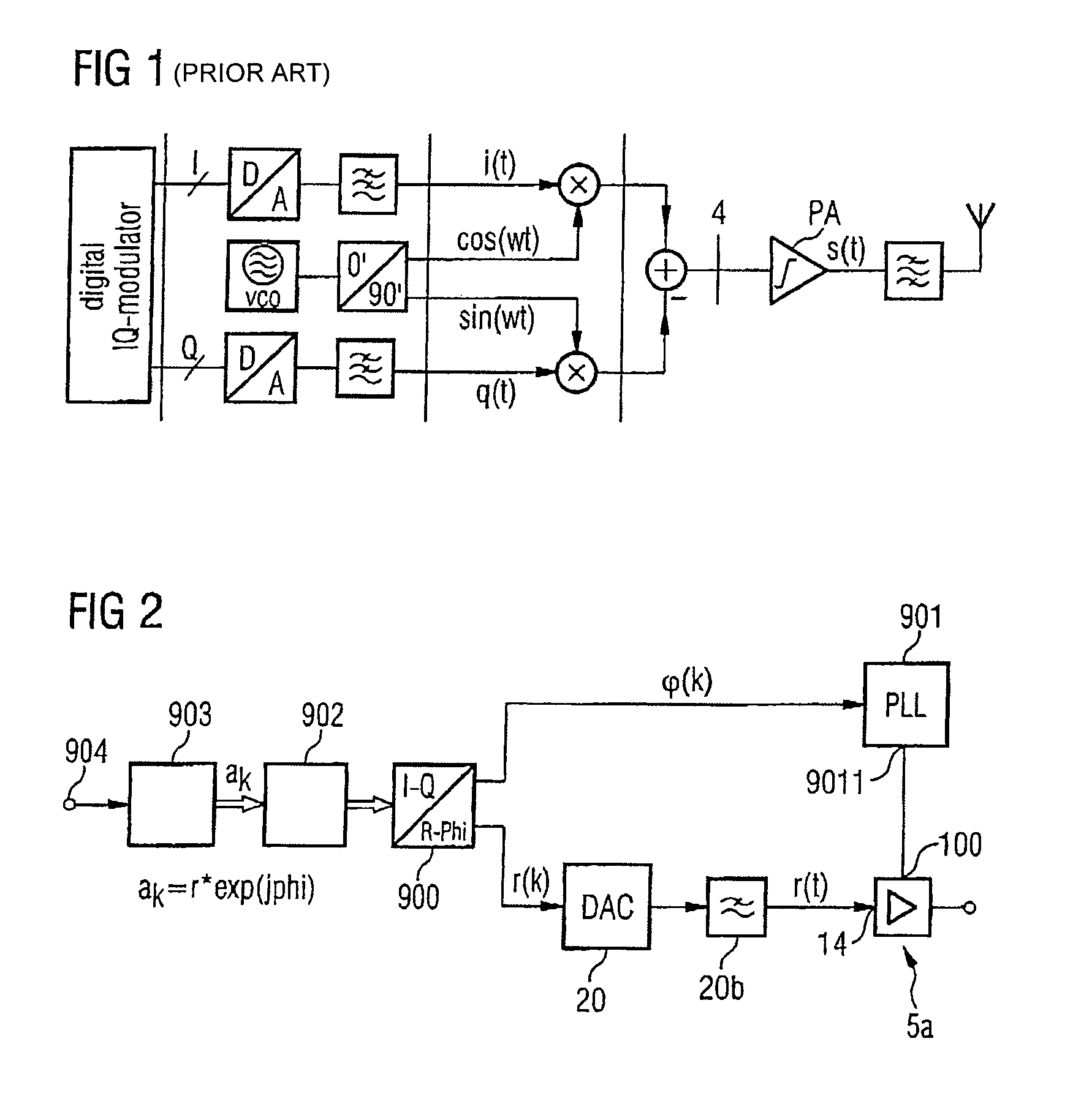
[0036]FIG. 2 shows a block diagram of a polar transmitter having an amplifier circuit according to one embodiment of the invention. The polar transmitter illustrated is in the form of an integrated circuit in a semiconductor body. The information to be transmitted is supplied to the input 904 of said polar transmitter in the form of a serial bit stream. The input 904 is connected to a coder circuit 903. The latter combines the bits, which are supplied to the input 904, to form symbols, the symbols corresponding to a selected type of modulation. The latter is in turn dependent on a mobile communications standard set. The symbols which have been combined in this manner are converted, in the circuit 902, into a digital in-phase component i and a digital quadrature component q.

[0037]In addition, they are conditioned for further signal processing and their higher-order repetition spectra are suppressed. The output of the circuit 902 is connected to a converting device 900. The latter use...


PUM


Abstract

An amplifier arrangement contains a first signal input for supplying a carrier signal, a second signal input for supplying an amplitude modulation word and an amplifier stage. The amplifier stage is connected to a reference potential connection and, by means of a control connection via a means for DC signal suppression, to the first signal input. A DC voltage converter having a first connection for supplying a potential is designed to convert the potential into a supply potential, which is variable over a period of time, on the basis of a control signal, and outputs the supply potential to the second connection of the amplifier stage. In addition, the amplifier arrangement comprises a digital / analog converter which is coupled to the control connection of the amplifier stage. The input of the converter is connected to the second signal input.

Description

REFERENCE TO RELATED APPLICATIONS[0001]This application claims the benefit of the priority date of German application DE 10 2005 034 440.2, filed on Jul. 22, 2005, the contents of which are herein incorporated by reference in their entirety.FIELD OF THE INVENTION[0002]The invention relates to an amplifier arrangement, in particular for polar transmitters. The invention also relates to a polar transmitter having an amplifier arrangement and to a method for amplifying signals.BACKGROUND OF THE INVENTION[0003]In many modern communications systems, the information to be transmitted is coded both in the phase and in the amplitude of a carrier signal. The combined coding of the information makes it possible to achieve considerably higher data transmission rates than in conventional types of modulation which use pure amplitude or phase modulation. Types of modulation which use pure phase modulation are referred to as types of modulation with a constant envelope (constant envelope modulatio...

Claims


Application Information

Patent Timeline
Patent Type & Authority Patents(United States)
IPC IPC(8): H04B1/04H01Q11/12
CPCH03G1/0088H03G3/004H04L27/20H04L27/361H03F1/223H03F1/3205H03F1/3241H03F3/245H03F3/2176H03F2200/18
Inventor EISENHUT, CARSTENSTEVANOVIC, NENADPUMA, GIUSEPPE LI
Owner APPLE INC
Why Eureka
Try Eureka