
Toner for developing electrostatic latent image and image forming method using the same

a technology of latent image and toner, which is applied in the field of toner for developing electrostatic latent image and image forming method using the same, can solve the problems of insufficient conventional magnetic toners generally used, inconvenient use, and high risk of magnetic toner leakage of electric charge, etc., and achieves high image quality, high endurability, and high resolution

Active Publication Date: 2009-08-18
KYOCERA DOCUMENT SOLUTIONS INC
View PDF6 Cites 2 Cited by
  • Summary
  • Abstract
  • Description
  • Claims
  • Application Information

AI Technical Summary

Benefits of technology

[0026]An object of the present invention is to provide a magnetic toner which can be rapidly charged and moreover improve the contradictory characteristics of obtaining the sufficient electric charge quantity and suppressing the over charge. Another object of the present invention is to form an excellent image under various environmental conditions. Other object of the present invention is to suppress the photoreceptor contamination as hardly as possible. Still another object of the present invention is to provide a magnetic toner which can endure various high stress uses.
[0031]According to the present invention, the toner which is of the high resolution, high image quality, is highly endurable and is strong against the environmental change, can be provided. Further, the imaging apparatus using the toner of the present invention is provided.
[0032]Concretely, according to the present invention, due to the novel shape of the magnetic particle, the electric charges of the magnetic toner rise up rapidly, the excessive charging is suppressed and the stability under the environmental change is improved. Further, due to the consideration of the sphericity and the fine particle content, the high endurance and high image quality are guaranteed. Furthermore, The externally added particle such as the charge control agents are made relatively large, thereby preventing the externally added particles from burying into the surface of the toner, thereby guaranteeing the endurance.

Problems solved by technology

However, the conventional magnetic toners generally used are not satisfactory in the current tendency seeking higher process speed and smaller-sized apparatus.
Such a magnetic toner is likely to leak the electric charge, because the electric charge is easily leaked from the vertexes and edges of the polyhedron.
Further, the magnetic polyhedrons do not well disperse, thereby fluctuating the charging characteristics.
Accordingly, the polyhedron magnetic toner has a disadvantage that the charge quantity does not rapidly rise up, resulting in a low charge quantity, the toner scattering & dropping and the image quality degradation such as the fogging in the image background.
Further, it has another disadvantage that the image quality is farther degraded in the high temperature and high humidity environment where the electric charging becomes difficult.
Accordingly, the electric charges are not easily discharged.
However, the spherical magnetic particle is easily charged so much that the excessive charge-up is easily caused and the image quality degradation such as the low image density is easily induced.
However, pointed lines are still left, thereby easily discharging from the pointed lines and therefore thereby possibly causing the low image density and the background fog.
However, it has a disadvantage that the magnetic toner is charged up similarly to the spherical magnetic toner, thereby possibly causing the image quality degradation.
First, the conventional toner wherein the magnetic powders are added in the inside of the toner has a disadvantage that it is not rapidly charged, is excessively charged up and is unstable against the environmental condition.
Second, it has another disadvantage that the internal portion of the solid image is not well transferred, if the toner sphericity is too low (i.e., far from the sphere), while the photoreceptor drum is not well cleaned due to the slipping of the toners through the cleaning blade, if the toner sphericity is too high (i.e., almost like sphere shaped).
Third, if the toner content of smaller than 2 μm is abundant, the toner charge distribution becomes broad, thereby resulting in the degrading of the background fog, the photoreceptor cleaning and the long term endurance.

Method used


Image

  • Toner for developing electrostatic latent image and image forming method using the same
  • Toner for developing electrostatic latent image and image forming method using the same
  • Toner for developing electrostatic latent image and image forming method using the same

Examples


Embodiment Construction

[0041]The preferred embodiments of the present invention are explained, referring to the drawings. It should be understood that the present invention is not limited to specifically described sizes, materials and relative arrangements and so on regarding the constituent components.

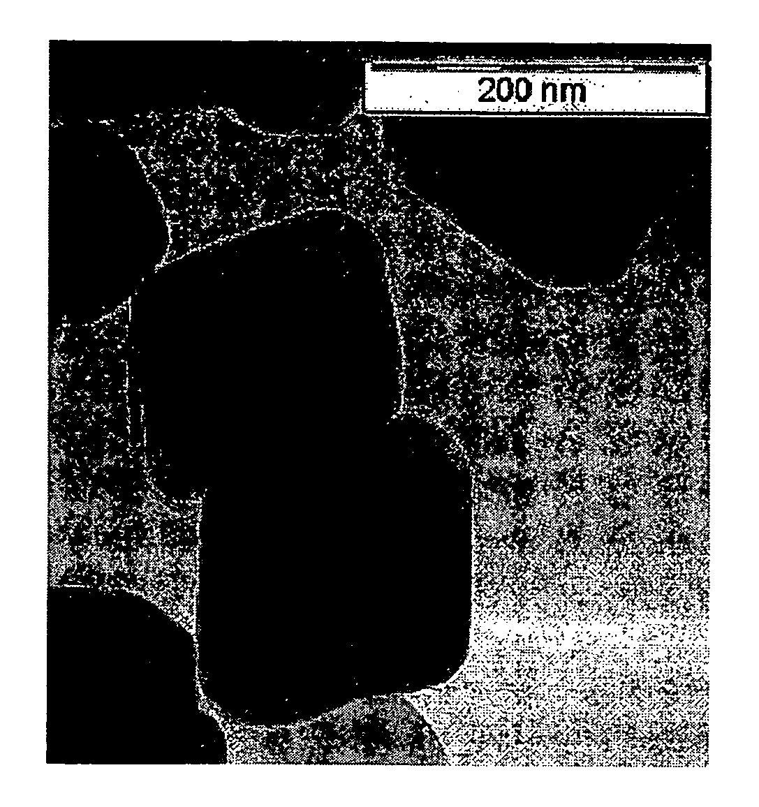
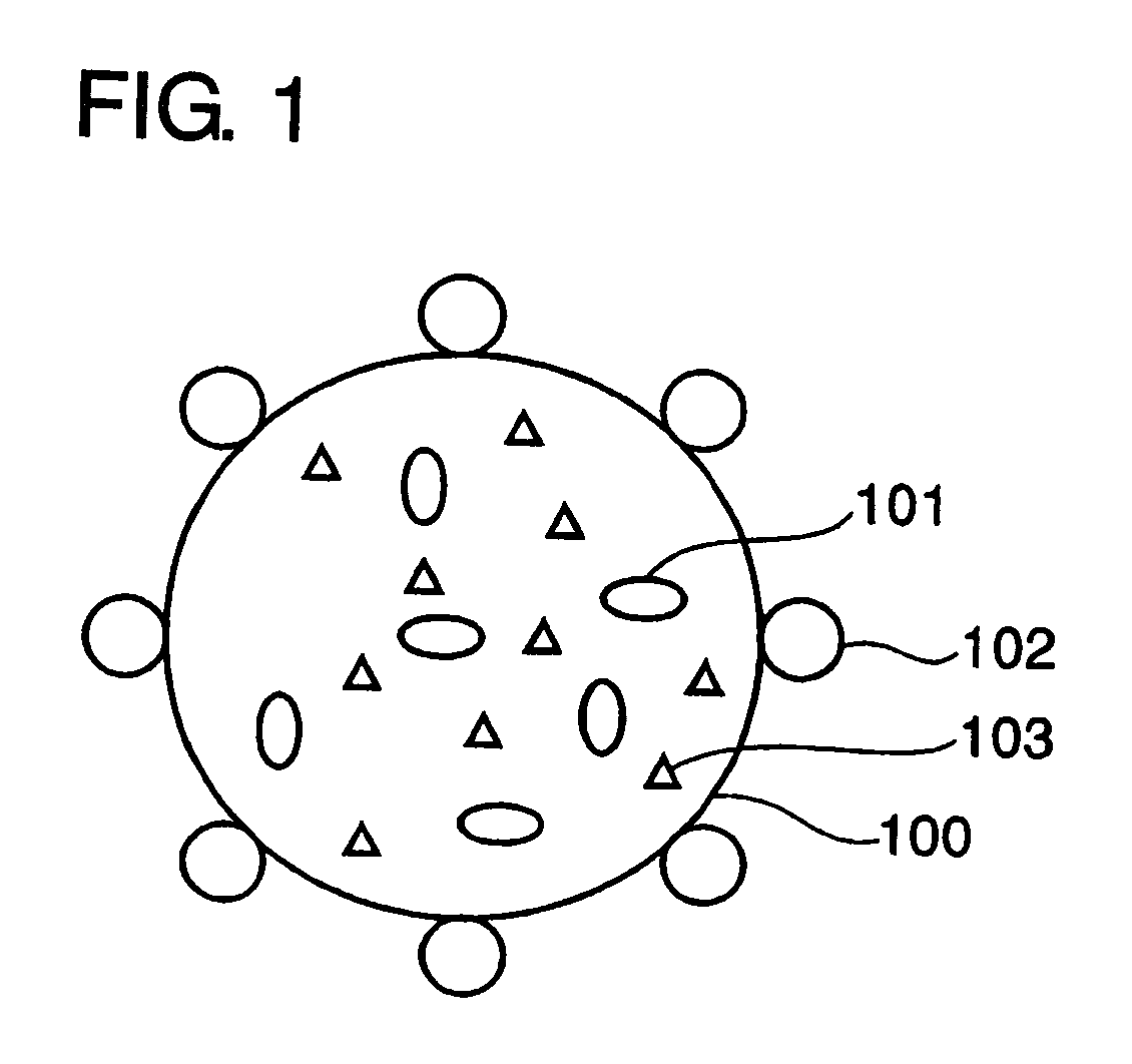
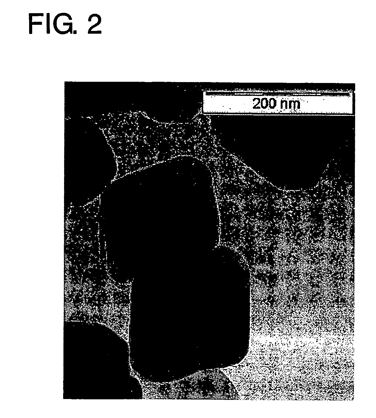
[0042]First, the magnetic particle contained in the toner of the present invention is explained, referring to FIG. 1 and FIG. 2.

Magnetic Particle

[0043]FIG. 1 is a schematic view of the toner of the present invention.

[0044]There are added in the toner 100 magnetic particles 101 and other particles 103. The magnetic particle 101 is of average size 0.01 μm through 0.50 μm and is of convex octahedron having eight triangle surfaces. Moreover, its vertexes and edges are not pointed but rounded. The projected image of the magnetic particle has linear portions at its outer circumference. The magnetic particle 101 is of magnetite including at least one element of 0.1 at. % through 10 at. % for Fe selected from Mn, Z...


PUM


Abstract

The toner of the present invention is characterized in that the charges rise up rapidly, the charge quantity is not insufficient nor excessive, the photoreceptor contamination is minimized and the toner is endurable under harsh conditions and against the high stress usage. The magnetic particle contained in the toner is of average particle size 0.01 μm through 0.50 μm, is of octahedron shape that is a convex polyhedron surrounded by eight triangles as a basis, each of vertexes and edges of the octahedron being in a curved surface shape and having a portion that can be taken as a straight line on the outer periphery of a projected image of said octahedron. The sphericity of the toner is 0.94 through 0.98. Here, the sphericity is defined by C2 / C1, where C1 is a circumferential length of an image projected on a plane and C2 is a circumferential length of an assumed circle area as same as that of the projected image. Further, a number content of the toner of particle size 0.6 μm through 2.0 μm is smaller than 10%.

Description

BACKGROUND OF THE INVENTION[0001](1) Field of the Invention[0002]The present invention relates to toner for developing electrostatic latent image and image forming method using the same, particularly to an optimization of the shape of a magnetic particle added in the toner and the shape of the toner.[0003](2) Description of the Prior Art[0004]In the electro-photographic image forming apparatuses such as laser printers, copiers, facsimiles and their hybrid apparatuses, first, the electrostatic latent image retaining member, i.e., a photoreceptor is electrically charged uniformly, second, the photoreceptor is exposed, thereby forming the electrostatic latent image, third, the latent image is developed by the toner, forth, the toner image is transferred onto the paper, or the intermediate transfer member, and finally the transferred toner image is fixed onto the paper.[0005]Although there are dry and wet developing methods, the dry development is more widely employed than the wet devel...

Claims


Application Information

Patent Timeline
Patent Type & Authority Patents(United States)
IPC IPC(8): G03G9/00
CPCG03G9/0835G03G9/0838G03G9/0837
Inventor TERAMOTO, KOUZOUNAKAYAMA, YUKINORISATOU, KOUSUKEMIZUHATA, HIROSHI
Owner KYOCERA DOCUMENT SOLUTIONS INC
Learn More