Method and apparatus for signature reduction using wavefront coding

a wavefront coding and wavefront technology, applied in the field of electronic and infrared devices, can solve the problem of typically remaining retro-reflection signals, and achieve the effect of reducing the amount of light and reducing the retro-reflection

Inactive Publication Date: 2009-08-18
UNITED STATES OF AMERICA THE AS REPRESENTED BY THE SEC OF THE ARMY
View PDF14 Cites 17 Cited by
  • Summary
  • Abstract
  • Description
  • Claims
  • Application Information

AI Technical Summary

Benefits of technology

[0009]Accordingly, one object of the present invention is to reduce the retro-reflectivity in infrared staring sensors, in particular forward looking infrared (FLIR) systems. The present invention achieves this objective by applying wavefront coding to minimize the amount of light that is retroreflected by the FLIR system back to its source. The present invention (unlike conventional retro-reflectivity reduction methods) does not rely on reducing the laser power leaving the interrogated sensor, but primarily on controlling its direction. A sensor according to the present invention, which has been wavefront coded for reduction of reflected light, will also effect the direction of the scattered light, thereby significantly reducing that which returns to the zero bistatic angle position. In contrast, a limitation of conventional methods is that once specular reflections are addressed, the remaining retroreflected signal typically results from scattered light at the focal plane, which is largely collected and recollimated by the system optics.

Problems solved by technology

In contrast, a limitation of conventional methods is that once specular reflections are addressed, the remaining retroreflected signal typically results from scattered light at the focal plane, which is largely collected and recollimated by the system optics.

Method used


Image

  • Method and apparatus for signature reduction using wavefront coding
  • Method and apparatus for signature reduction using wavefront coding
  • Method and apparatus for signature reduction using wavefront coding

Examples


Embodiment Construction

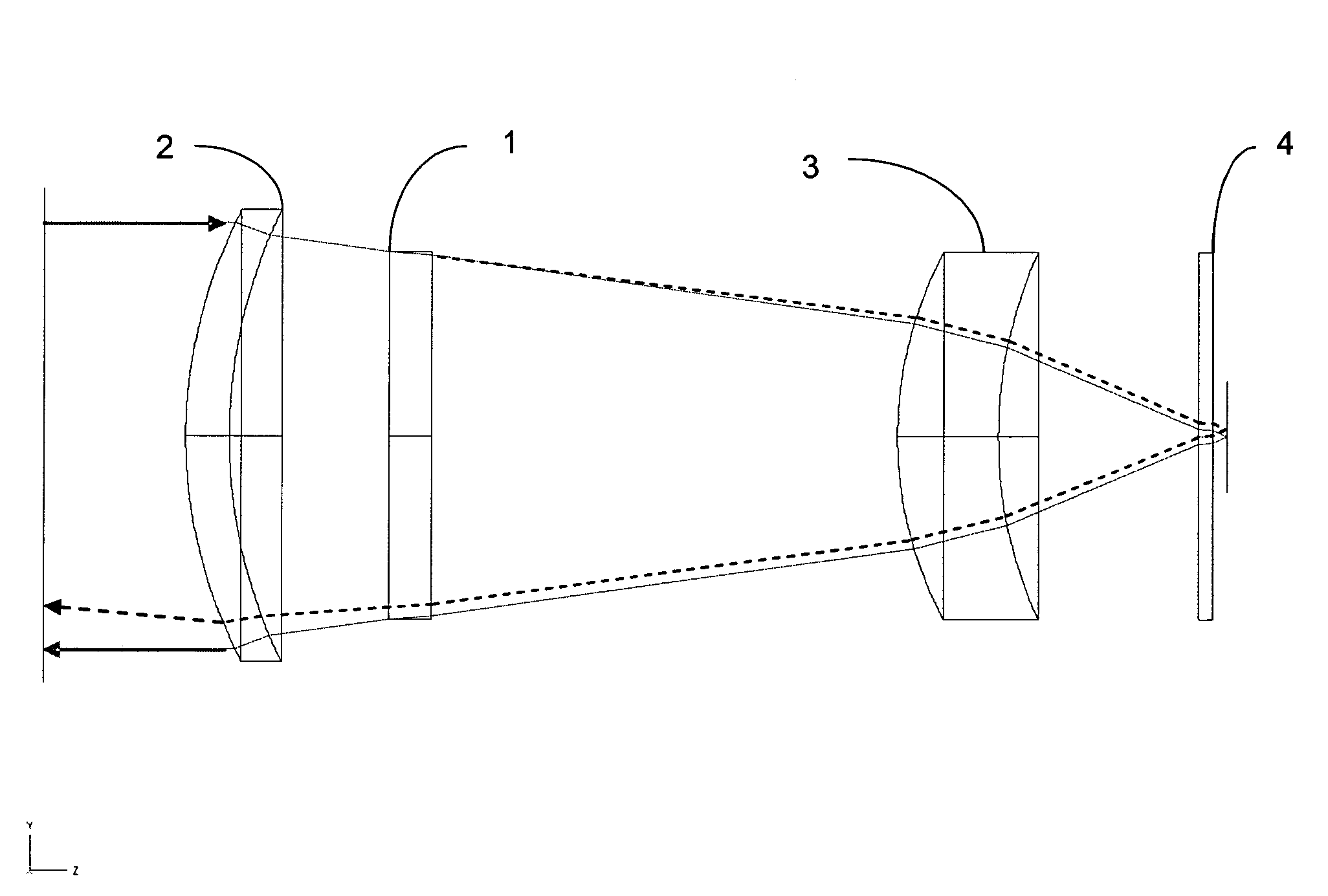
[0013]The invention applies wavefront coding to an Electro-Optic / Infrared (EO / IR) device (for example, an infrared staring sensor) such that the retroreflected wavefront can be modified to reduce the signature of the device. Implicit in the wavefront coding technique is the ability to code the wavefront to a specific advantage and then decode it through signal processing. In this case, the advantage is to minimize the amount of light that is retroreflected by a sensor back to its source.

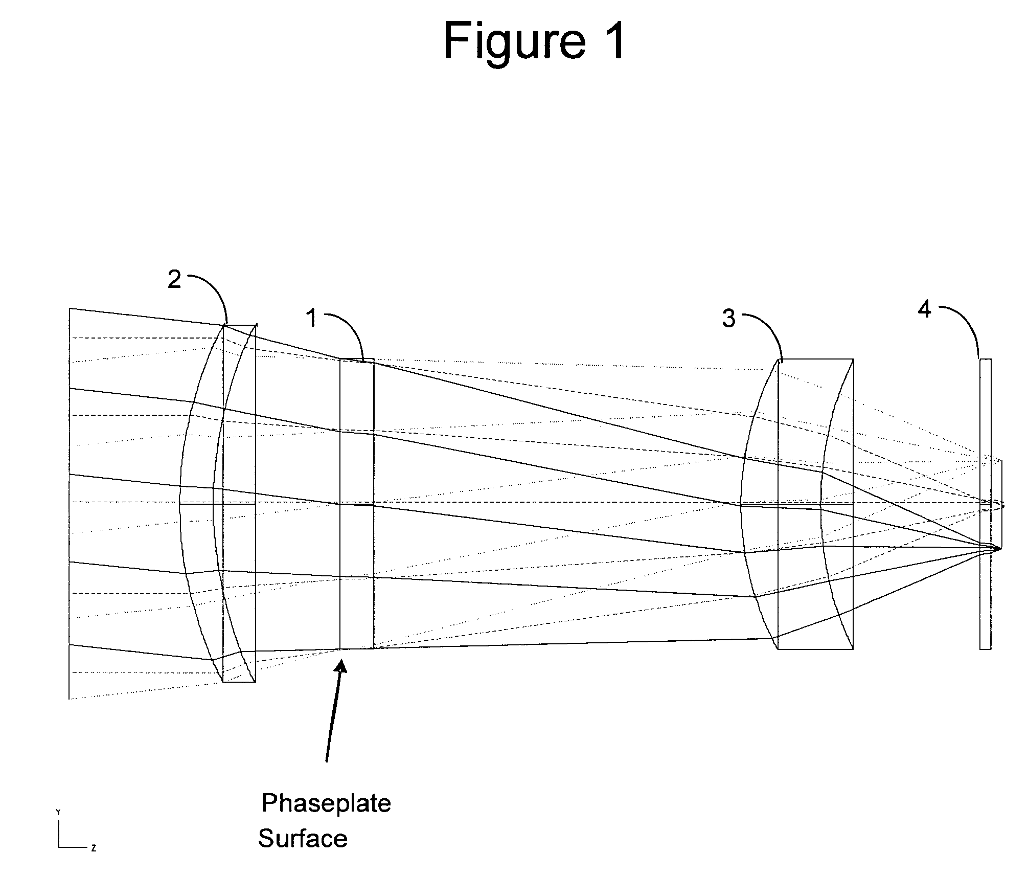
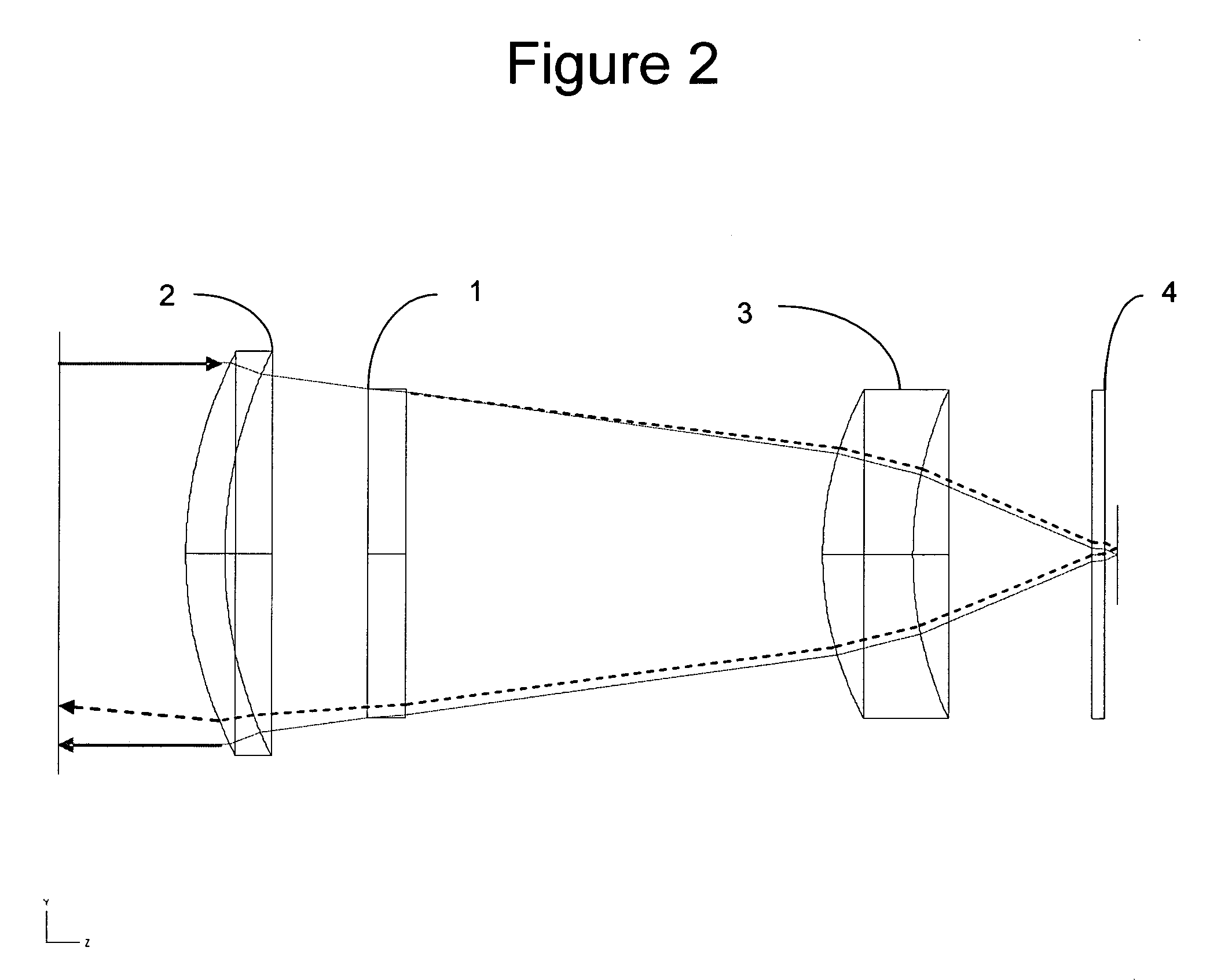
[0014]FIGS. 1 and 2 show a preferred embodiment of the invention. FIG. 1 shows an optical train with an optical phase plate at the pupil. Several fields are shown passing through the system and on to the FPA. FIG. 1 illustrates the position of the phase plate but not its effects on the transmitted rays. FIG. 2 illustrates the operation of the optical system on-axis both with and without the effects of the phase plate for retroreflection reduction. During normal operation of the optical system, a ray ...


PUM


Abstract

The invention applies wavefront coding to the front of an electro-optic / infrared device to minimize the amount of light which is retroreflected by systems, such as Fowarding Looking Infrared systems, back to its source. The invention (unlike conventional reduction methods) does not rely on reducing the laser power leaving the interrogated sensor, but primarily on controlling its direction. A sensor according to the present invention, which has been wavefront coded for reduction of reflected light, will also effect the direction of the scattered light, thereby significantly reducing that which returns to the zero bistatic angle position. In contrast, a limitation of conventional methods is that once specular reflections are addressed, the remaining retroreflected signal typically results from scattered light at the focal plane which is largely collected and recollimated by the system optics.

Description

GOVERNMENT INTEREST[0001]The invention described herein may be manufactured, used, sold, imported, and / or licensed by or for the Government of the United States of America.FIELD OF INTEREST[0002]This invention relates to electro-optic and infrared devices and reducing the retro-reflectivity of these devices and in particular of Forward Looking Infrared (FLIR) systems.BACKGROUND OF THE INVENTION[0003]Infrared (IR) staring sensors are well known in the prior art for obtaining data in the IR spectrum. Typically, these sensors include an optical train that minimizes the optical blur spot at the focal plane. The optical train receives the optical rays through an aperture, and then directs the incoming IR optical rays onto a focal plane array (FPA) for further processing and display by other components of the device. One of the disadvantages of these devices, however, is that during operation, a portion of the incoming IR radiation actually reflects off the focal plane array, passes back ...

Claims


Application Information

Patent Timeline
Patent Type & Authority Patents(United States)
IPC IPC(8): H04N5/225G01J5/02
CPCG02B13/14G02B23/12G02B13/16
Inventor SONSTROEM, JAIME
Owner UNITED STATES OF AMERICA THE AS REPRESENTED BY THE SEC OF THE ARMY
Why Eureka
Try Eureka