Wastewater treatment equipment and method of wastewater treatment
a wastewater treatment equipment and wastewater technology, applied in the direction of water/sewage treatment by ion exchange, settling tank feed/discharge, treatment water, etc., can solve the problems of nanobubbles not being generated, microbubbles not being produced, etc., to enhance improve the efficiency of wastewater treatment, and produce stably and efficiently
- Summary
- Abstract
- Description
- Claims
- Application Information
AI Technical Summary
Benefits of technology
Problems solved by technology
Method used
Image

Examples
first embodiment
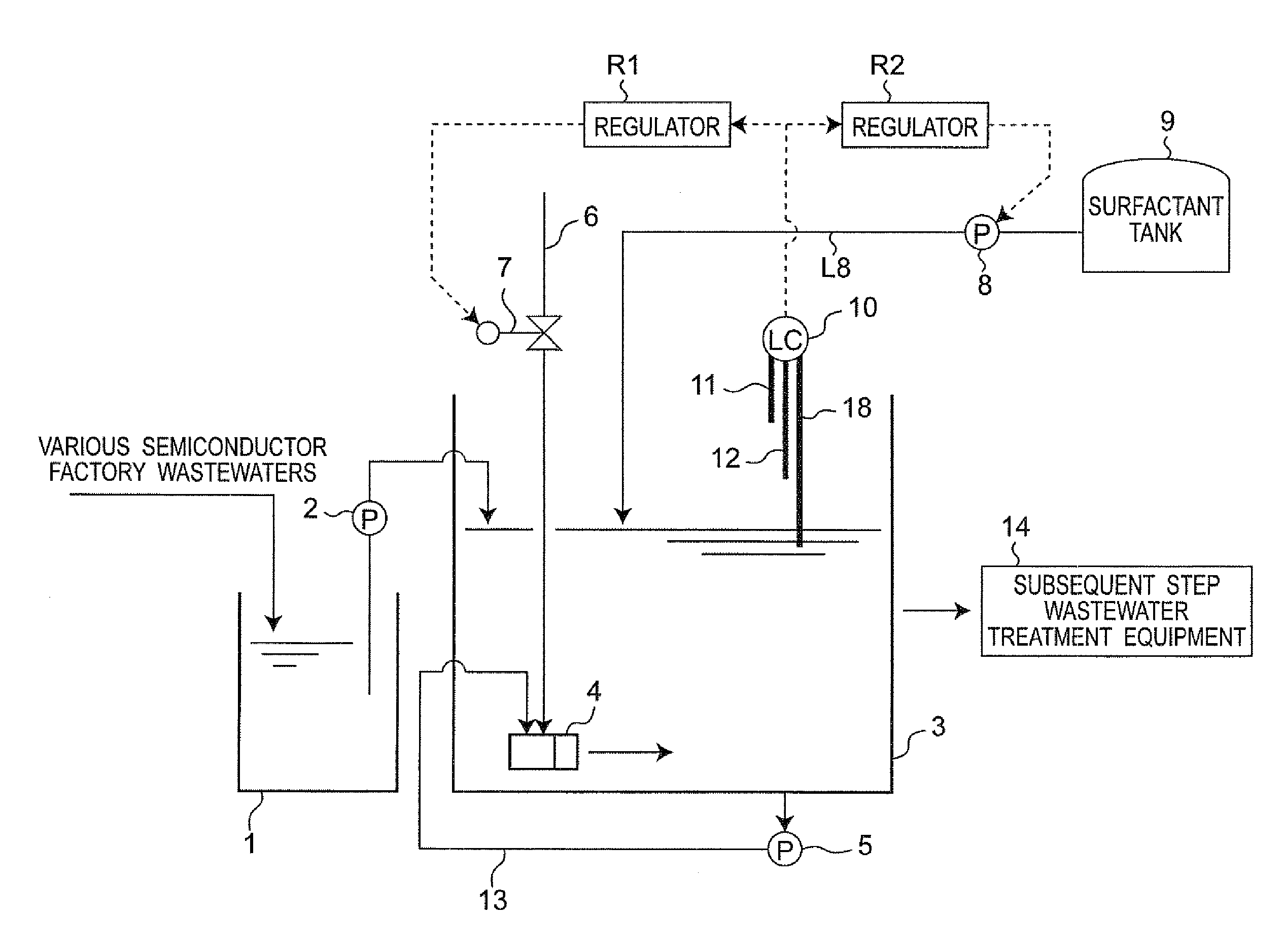
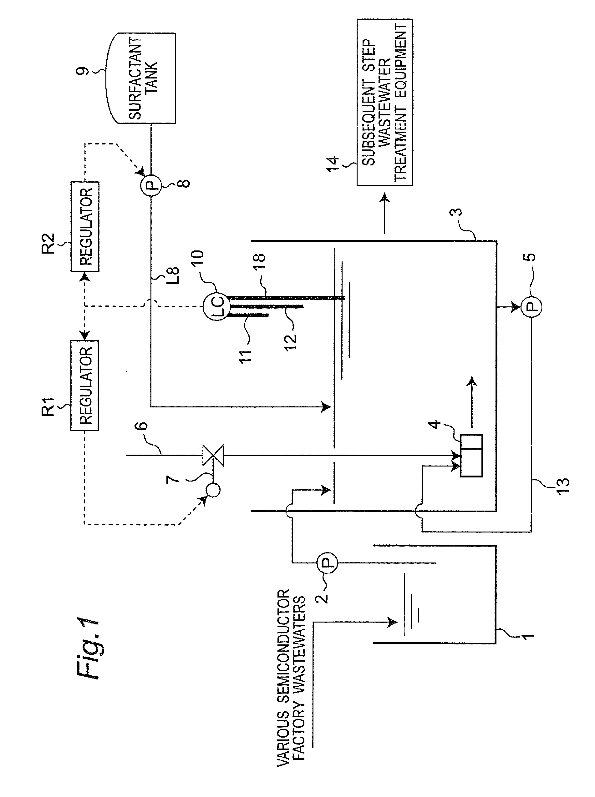
[0078]FIG. 1 shows a schematic view of wastewater treatment equipment in a first embodiment of the present invention. The wastewater treatment equipment in the first embodiment is composed of an adjustment tank 1, a micronanobubble reaction vessel 3 having a micronanobubble generator 4, a surfactant pump 8 and a surfactant tank 9 which constitute a surfactant adding section, and subsequent step wastewater treatment equipment 14 as a wastewater treatment section in a subsequent step.
[0079]In the present embodiment, for example, various semiconductor factory wastewaters are introduced into the adjustment tank 1, so as to adjust quantity and quality of the various semiconductor factory wastewaters therein. The semiconductor factory wastewaters introduced into the adjustment tank 1 are waste liquids containing organic matter like developer waste, wastewater containing fluorine as acid wastewater, or ammonium wastewater as alkaline wastewater. The wastewaters introduced into the adjustme...
second embodiment
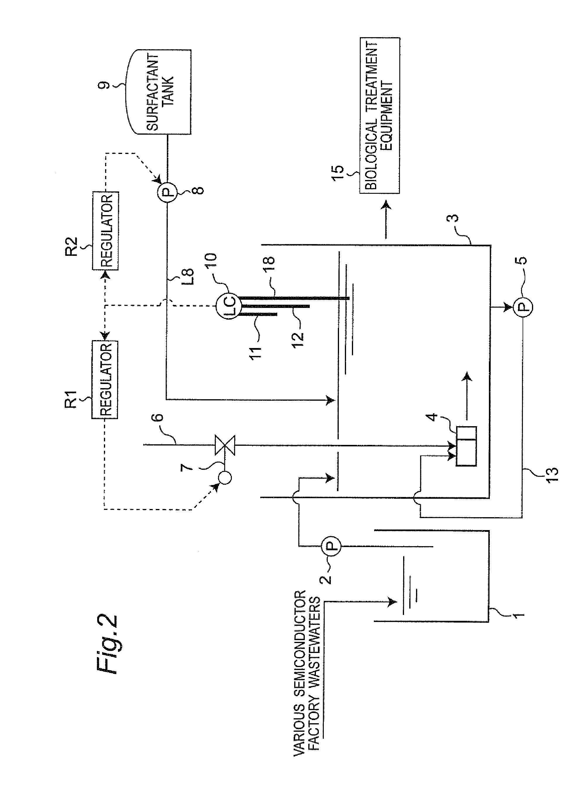
[0099]Next, FIG. 2 shows wastewater treatment equipment in a second embodiment of the present invention. The second embodiment is different from the above-stated first embodiment only in the point that biological treatment equipment 15 is installed in place of the subsequent step wastewater treatment equipment 14 placed subsequent to the micronanobubble reaction vessel 3 in the first embodiment. Consequently, in the second embodiment, the component parts identical to those in the first embodiment are designated by identical reference numerals, and description will be omitted except the component parts different from the first embodiment.
[0100]Micronanobubbles particularly have not only the property of oxidizing organic matter but also the property of continuously maintaining dissolved oxygen in water with use of nanobubbles. According to the present embodiment, therefore, it becomes possible to reduce a load of treating organic matter on the biological treatment equipment 15 which i...
third embodiment
[0102]FIG. 3 shows wastewater treatment equipment in a third embodiment of the present invention. The third embodiment is different from the above-stated first embodiment only in the point that chemical treatment equipment 16 is installed in place of the subsequent step wastewater treatment equipment 14 placed subsequent to the micronanobubble reaction vessel 3 in the first embodiment. Consequently, in the third embodiment, the component parts identical to those in the first embodiment are designated by identical reference numerals, and description will be omitted except the component parts different from the first embodiment.
[0103]It has been known that the micronanobubbles act in a catalytic way to advance chemical reaction. According to the third embodiment, therefore, the catalytic action of the micronanobubbles makes it possible to faster advance the chemical reaction in the chemical treatment equipment 16 placed subsequent to the micronanobubble reaction vessel 3 than the norm...
PUM
| Property | Measurement | Unit |
|---|---|---|
| diameter | aaaaa | aaaaa |
| diameter | aaaaa | aaaaa |
| size | aaaaa | aaaaa |
Abstract
Description
Claims
Application Information
 - R&D
- Intellectual Property
- Life Sciences
- Materials
- Tech Scout
- Unparalleled Data Quality
- Higher Quality Content
- 60% Fewer Hallucinations
Browse by: Latest US Patents, China's latest patents, Technical Efficacy Thesaurus, Application Domain, Technology Topic, Popular Technical Reports.
© 2025 PatSnap. All rights reserved.Legal|Privacy policy|Modern Slavery Act Transparency Statement|Sitemap|About US| Contact US: help@patsnap.com