Ground fault detection device for motor driving circuit

a technology for driving circuits and ground faults, which is applied in the direction of motor/generator/converter stoppers, motor/electric converter control, instruments, etc., can solve the problems of increasing the number of electric-current detection operational amplifiers and devices, increasing the heat generated by resistances, and inconvenience of degradation of inverter circuit efficiency, so as to detect ground faults without degrading efficiency, without complicating circuit structur

Inactive Publication Date: 2009-09-08
OMRON AUTOMOTIVE ELECTRONICS CO LTD
View PDF18 Cites 42 Cited by
  • Summary
  • Abstract
  • Description
  • Claims
  • Application Information

AI Technical Summary

Benefits of technology

[0010]Namely, operational amplifiers (differential amplification circuits) are used for detecting electric currents and, in order to detect an electric current with the second electric-current detection resistance, a power-supply voltage should be input to an operational amplifier, which necessitates selection of an operational amplifier with excellent performance in common mode rejection ratio CMR indicating the ratio between the variation of the input voltage and the variation of an input offset voltage (DC variation, in general), thereby involving higher cost. Furthermore, the second electric-current detection resistance should be used in addition to the first electric-current detection resistance, which further increases the numbers of electric-current detection operational amplifiers and devices in their peripheral circuit structures, thereby complicating the circuit structure and also increasing the amount of heat generated from resistances. This has induced inconvenience of degradation of the efficiency of the inverter circuit.
[0018]As described above, according to the present invention, the electric current energy which has been accumulated, during the first time interval, in the inductance distribution (parasitic inductance) between the inverter circuit and the position of a ground fault is detected with the electric-current detection resistances during the first regenerative time interval, which eliminates the necessity of providing a second electric-current detection resistance for detecting ground faults, as in Japanese Patent Application Laid-Open No. 6-233450. This enables detection of ground faults, without complicating the circuit structure and without degrading the efficiency.
[0019]According to the present invention, it is possible to detect ground faults with a simple circuit structure, without reducing the efficiency of the inverter circuit.

Problems solved by technology

With the device described in Japanese Patent Application Laid-Open No. 6-233450 described above, it is possible to detect the occurrences of excessive electric currents and ground faults in the inverter circuit, but there is a need for connecting the second electric-current detection resistance between the power-supply connection terminals of the upper switching devices and the power supply, thus inducing inconvenience as follows.
Furthermore, the second electric-current detection resistance should be used in addition to the first electric-current detection resistance, which further increases the numbers of electric-current detection operational amplifiers and devices in their peripheral circuit structures, thereby complicating the circuit structure and also increasing the amount of heat generated from resistances.
This has induced inconvenience of degradation of the efficiency of the inverter circuit.

Method used


Image

  • Ground fault detection device for motor driving circuit
  • Ground fault detection device for motor driving circuit
  • Ground fault detection device for motor driving circuit

Examples


Embodiment Construction

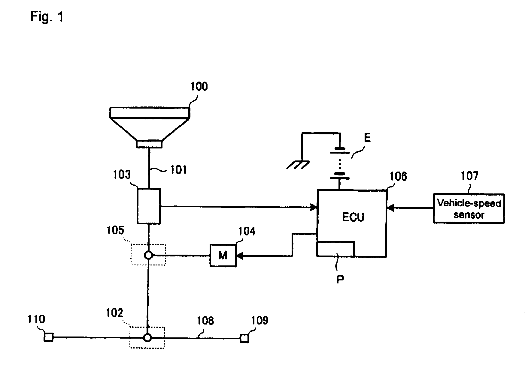
[0029]FIG. 1 is a view illustrating the general structure of an electric power steering device which used in the present invention.

[0030]The electric power steering device includes a handle 100 for steering, a steering shaft 101 secured at its one end to the handle 100, a rack and pinion mechanism 102 coupled to the other end of the steering shaft 101, a torque sensor 103 provided in a portion of the steering shaft 101 for detecting the steering torque which is applied to the steering shaft 101 through operations on the handle 100, and a worm wheel mechanism 105 for applying, to the steering shaft 101, the rotational driving force from a three-phase brushless motor (hereinafter, refereed to as a motor) 104 as a steering assist force (steering aiding force).

[0031]The torque sensor 103, the motor 104 and a vehicle-speed sensor 107 are connected to a vehicular electronic control unit (ECU) 106, wherein the ECU 106 controls the driving electric current of the motor 104 on the basis of d...


PUM


Abstract

A motor driving circuit includes an inverter circuit including switching devices connected in a bridge manner, electric-current detection resistances connected between the lower switching devices in the inverter circuit and the ground, so as to enable detection of the phase currents with the electric-current detection resistances, a PWM circuit which controls ON / OFF of the switching devices and repeatedly causes powering and regenerative time intervals, by alternately turning on and off the upper switching devices and the lower switching devices. During a time interval during which the lower switching devices, the electric-current detection resistances and the motor constitute a closed circuit and a regenerated electric current flows through the circuit, when the electric current values detected are equal to or greater than a predetermined electric current value, it is determined that a ground fault has occurred in the connection lines between the inverter circuit and the motor.

Description

BACKGROUND OF THE INVENTION[0001]1. Field of the Invention[0002]The present invention relates to a device for detecting ground faults in an inverter device for driving a brushless motor used in an electric power steering device for a vehicle and, more particularly, to a motor-driving-circuit ground-fault detection device for detecting ground faults in connection lines between a motor and an inverter circuit.[0003]2. Description of the Related Art[0004]An electric power steering device for a vehicle is provided with a motor such as a three-phase brushless motor, in order to apply, to a steering mechanism, a steering aiding force corresponding to the steering torque of a handle. The steering torque applied to the handle is detected by a torque sensor and, on the basis of the detected value, target values of electric currents to be flowed through the motor are calculated. Then, on the basis of the deflections between the target values and the values of the electric currents actually fl...

Claims


Application Information

Patent Timeline
Patent Type & Authority Patents(United States)
IPC IPC(8): H02P3/18B60R16/02B62D5/04B62D6/00B62D119/00H02P27/06H02P27/08H02P29/00
CPCB62D5/0487G01R31/025H02P29/021H02H7/0838H02H3/165H02P29/0241G01R31/52
Inventor GUNJI, KEITA
Owner OMRON AUTOMOTIVE ELECTRONICS CO LTD
Why Eureka
Try Eureka