Coil device and nuclear magnetic resonance imaging apparatus using the same
a nuclear magnetic resonance imaging and coil technology, applied in the direction of measuring devices, magnetic measurements, instruments, etc., can solve the problems of increasing the complexity of circuit tuning, the uniformity of effective sensitivity declines, and the difficulty of application to large coils, so as to achieve uniform sensitivity. the effect of the rang
- Summary
- Abstract
- Description
- Claims
- Application Information
AI Technical Summary
Benefits of technology
Problems solved by technology
Method used
Image
Examples
example 1
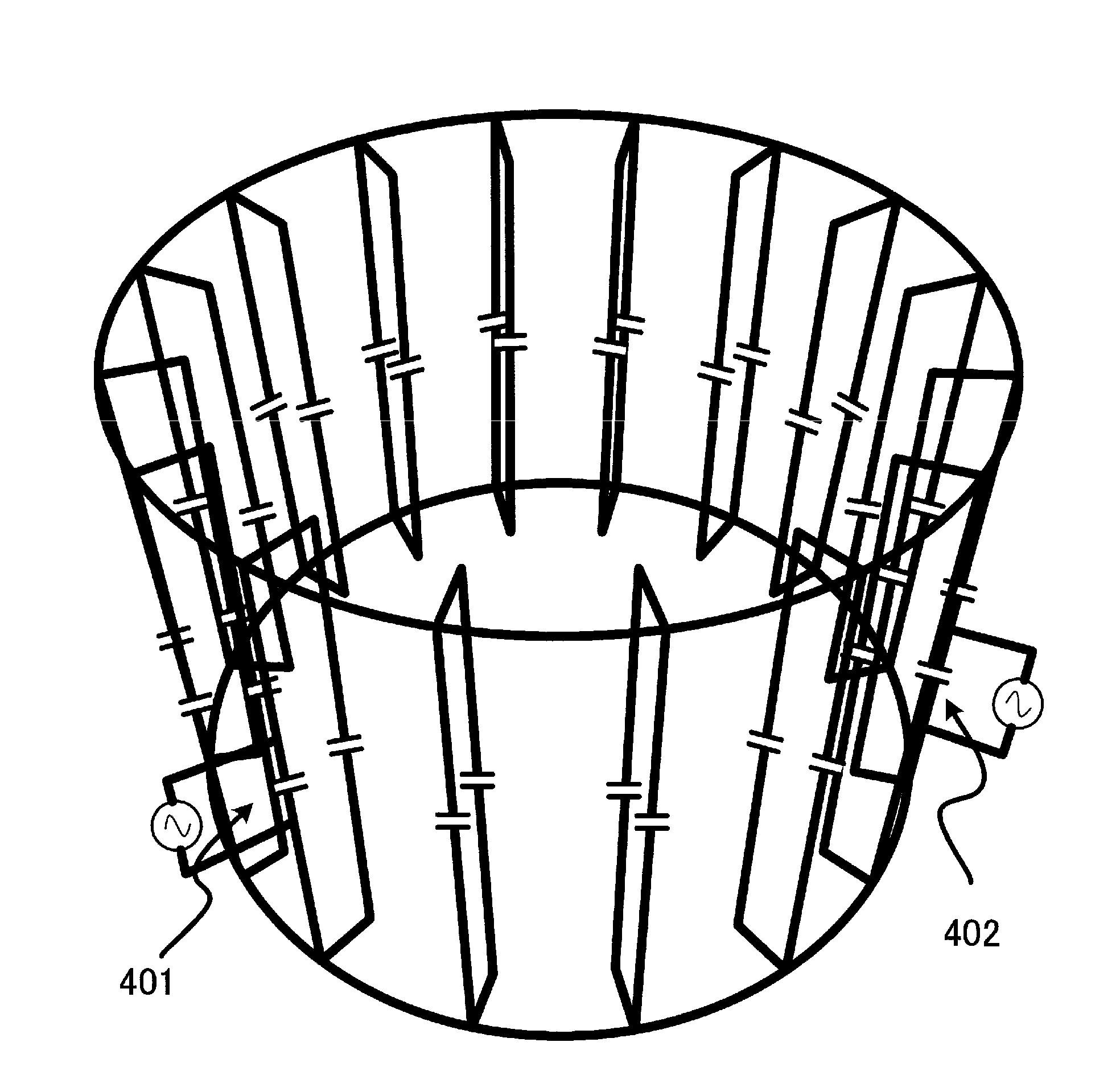
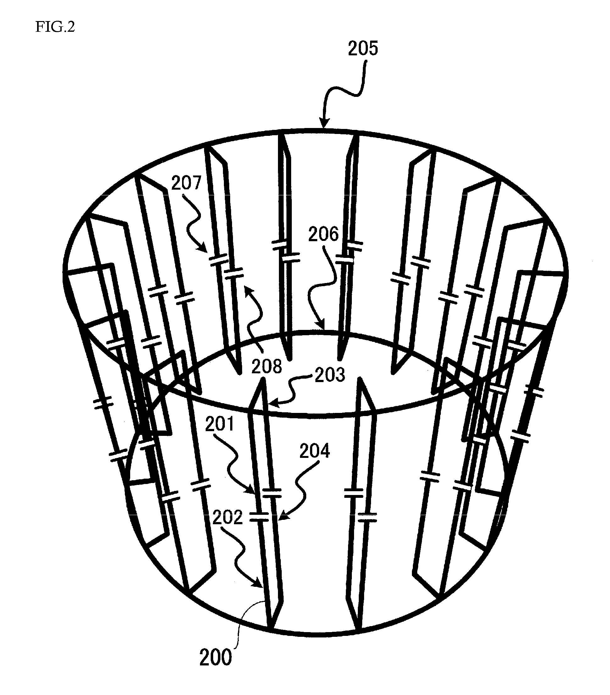
[0085]An example, in which the RF coil made of 16 first coils and second coils, as shown in FIG. 2, are installed in the MRI apparatus with the magnetic field strength of 3 Tesla to obtain hydrogen and carbon signals, will be explained.
[0086]In the present example, the coil was designed to have an axial length of 220 millimeter, outer diameter of about 334 millimeter and internal diameter of approximately 276 millimeter. Also, the value, C1, of the first condenser 207 sandwiched between the first conducting sections of the first coil was set at 17 pF, and the value, C2, of the condenser 208 between second conducting sections was set at 12 pF. Since the use of a copper rod of 4 millimeter in radius is assumed, the electric conductivity of copper was used.
[0087]Resonance characteristics of this RF coil obtained by simulation are shown in FIG. 8, where the horizontal and vertical axes represent the frequency and the impedance, respectively. The impedance was obtained by simulating the ...
example 2
[0097]This example explains concrete configuration of dual-frequency tuning coil which can be tuned with the frequencies of hydrogen and phosphor in the 3-Tesla MRI apparatus as in Example 1.
[0098]The RF coil of this example is, as in Example 1, the RF coil in the shape shown in FIG. 2. However, it is different from Example 1 in that the condenser 301 is inserted into the ring-shaped part of the second coil and its value was set at 250 pF. As mentioned earlier, by inserting the condenser into the ring-shaped part of the second coil, the tuning frequency of bird cage type can be raised. The simulation of resonance characteristics of the RF coil of this example revealed that the addition of the condenser 301 of 250 pF into the ring-shaped part of the RF coil in Example 1 could alter the bird cage type tuning frequency from 32 MHz to 52 MHz while maintaining the multiple patch resonator type tuning frequency at 129 MHz. The frequency of 52 MHz is almost identical with the tuning freque...
example 3
[0099]Resonance characteristics of the RF coil, in which two conducting parts of the first conducting section connected via the condenser 207 are connected with one conductor into one conductor without using the condenser 207 in Example 2, was examined. Other elements of the configuration were same with those of Example 2. Feeding was performed in parallel with the condenser 208 or 301 among the multiple number of condensers.
[0100]Simulation of the RF coil of this Example show that the bird cage type resonance mode appears, like the RF coil in examples 1 and 2, at the lower frequency range than that of the multiple patch resonator type resonance mode, and that the bird cage mode of high pass type appeared instead of the bird cage mode of low pass type in Example 1.
[0101]It was found that if the value C2 of the condenser 208 inserted into the second conducting section (inside the rung) is set at 5.8 pF, and the value of the condenser 301 of the second coil (ring part) at 119.7 pF, a ...
PUM
 Abstract
Description
Claims
Application Information
 - R&D
- Intellectual Property
- Life Sciences
- Materials
- Tech Scout
- Unparalleled Data Quality
- Higher Quality Content
- 60% Fewer Hallucinations
Browse by: Latest US Patents, China's latest patents, Technical Efficacy Thesaurus, Application Domain, Technology Topic, Popular Technical Reports.
© 2025 PatSnap. All rights reserved.Legal|Privacy policy|Modern Slavery Act Transparency Statement|Sitemap|About US| Contact US: help@patsnap.com


