Self referencing heterodyne reflectometer and method for implementing

a heterodyne reflectometer and self-referencing technology, applied in the field of refractive measurements, can solve the problems of affecting the accuracy of the results, unable to measure or calculate the actual thickness parameter of the film layer, and the bandwidth of the source and thinnest film measurable is limited, so as to achieve high-quality phase shift information

Active Publication Date: 2009-09-15
VERITY INSTR
View PDF15 Cites 8 Cited by
  • Summary
  • Abstract
  • Description
  • Claims
  • Application Information

AI Technical Summary

Problems solved by technology

Thus, the accuracy of the results is adversely affected by surface roughness.
Another limitation of the prior art common axis method is that it does not measure or calculate an actual thickness parameter for a film layer.
The principle drawback of these types of devices is that since the heterodyning is achieved by frequency modulating, the source and thinnest film measurable is limited by its bandwidth.

Method used


Image

  • Self referencing heterodyne reflectometer and method for implementing
  • Self referencing heterodyne reflectometer and method for implementing
  • Self referencing heterodyne reflectometer and method for implementing

Examples


Embodiment Construction

Element Reference Number Designations

[0036]

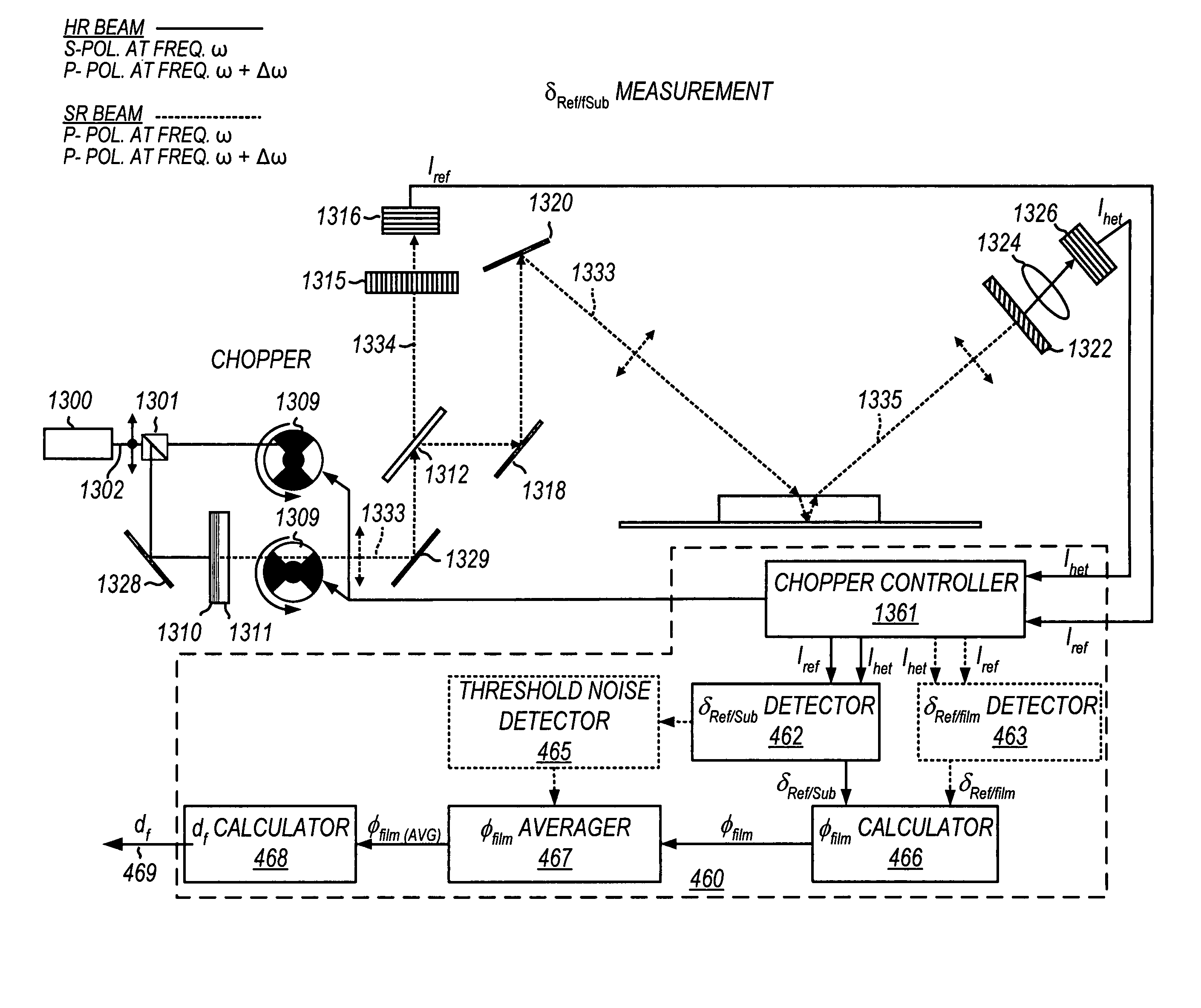
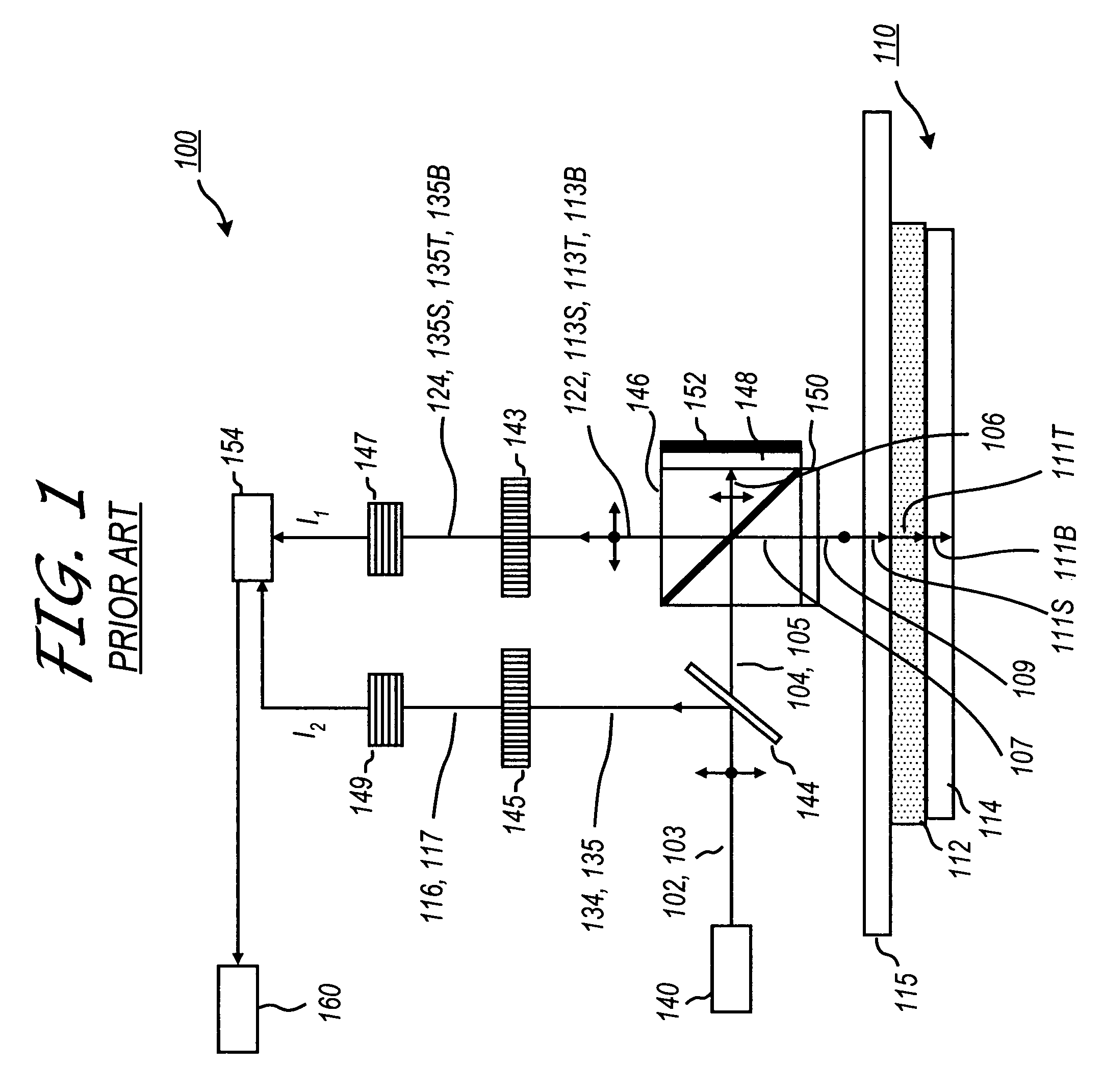
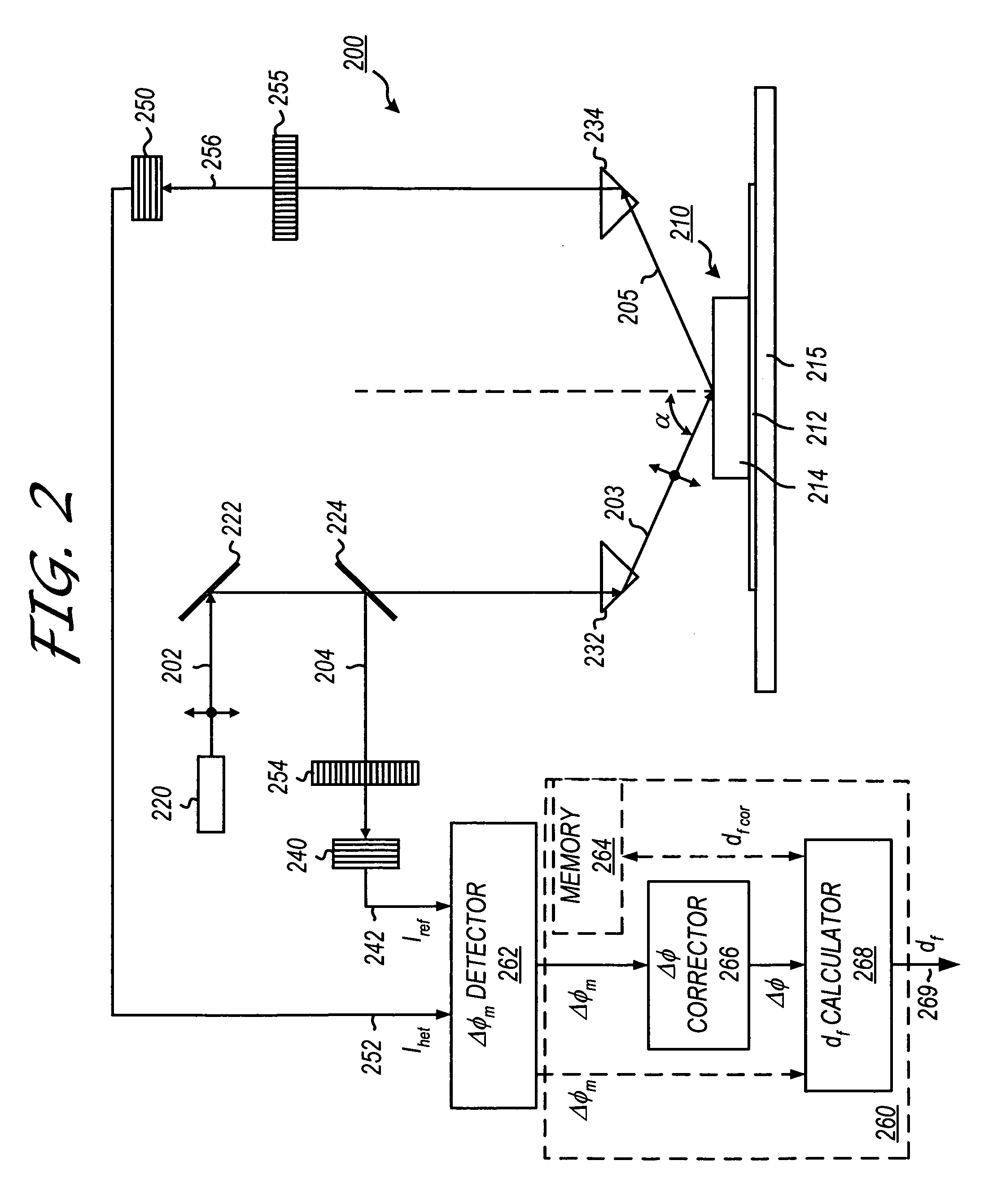
100:Heterodyne monitoring system102:First linear polarized light component102:First linear polarized light component103:Second linear polarized component104:First polarization component105:Second polarization component106:Orthogonally polarized to beam107:Beam109:Beam110:Wafer111s:Reflected beam111b:Reflected beam111t:Reflected beam112:Substrate113s:Beam113b:Beam113t:Beam114:Film115:Rotatable carrier116:Beam117:Beam122:Beam124:Beam134:Beam135:Beam135S:Beam135B:Beam135T:Beam140:Laser diode143:Mixing polarizer144:Beam splitter145:Mixing polarizer146:Polarization beam splitter147:Photo detector148:Quarter-wave plate149:Photo detector150:Quarter-wave plate152:Beam reflector154:Signal-processing assembly160:Data processing system200:Heterodyne reflectometer202:Split freq. beam with orthogonal, linearly polarized components203:Incident beam204:Split beam205:Reflected beam210:Table system212:Substrate214:Film215:Table220:Light source222:Optics224:...


PUM


Abstract

A self referencing heterodyne reflectometer is disclosed which rapidly alternates between a heterodyne reflectometry (HR) mode, in which an HR beam comprised of s- and p-polarized beam components at split angular frequencies of ω and ω+Δω is employed, and a self referencing (SR) mode, in which an SR beam comprised of p-polarized beam components at split angular frequencies of ω and ω+Δω is employed. Alternatively, in SR operating mode the SR beam is replaced by a p-polarized amplitude modulated (AM) beam, operating at two modulated amplitudes of α and α+Δα at a single frequency, ω′. When the two measurements are made in rapid succession, using an optical chopper switcher, temperature induced noise in the detector is be assumed to be equivalent. Film phase shift information is derived from the measured phase shift δRef / film, generated from the HR beam, and the reference phase shift δRef / Sub, generated from the SR / AM beam, which are used for calculating film thickness.

Description

CROSS REFERENCES TO RELATED APPLICATIONS[0001]This application is a Continuation-In-Part of U.S. patent application Ser. No. 11 / 237,225 entitled “Self Referencing Heterodyne Reflectometer and Method for Implementing,” filed Sep. 27, 2005 now U.S. Pat. No. 7,545,503. The present application is related to co-pending U.S. patent application Ser. No. 11 / 178,856 entitled “Method for Monitoring Film Thickness Using Heterodyne Reflectometry and Grating Interferometry,” filed Jul. 10, 2005, and co-pending U.S. patent application Ser. No. 11 / 066,933 entitled “Heterodyne Reflectometer for Film Thickness Monitoring and Method for Implementing,” filed Feb. 25, 2005, both assigned to the assignee of the present application. The above identified applications are incorporated by reference herein in their entireties.BACKGROUND OF THE INVENTION[0002]The present invention relates to reflectometry. More particularly, the present invention relates to a reflectometer system and method for obtaining thic...

Claims


Application Information

Patent Timeline
Patent Type & Authority Patents(United States)
IPC IPC(8): G01B11/02G01B9/02
CPCG01B11/0675G01B9/02003G01B9/02022G01B9/02057G01B2290/60G01B2290/70
Inventor AIYER, ARUN ANANTHMELONI, MARK A.
Owner VERITY INSTR
Why Eureka
Try Eureka