
Method and apparatus for mounting photovoltaic modules

a photovoltaic module and mounting method technology, applied in the field of photovoltaic modules, to achieve the effect of cost-effectiveness

Active Publication Date: 2009-09-22
TESLA INC
View PDF7 Cites 316 Cited by
  • Summary
  • Abstract
  • Description
  • Claims
  • Application Information

AI Technical Summary

Benefits of technology

[0039]The method and apparatus for mounting photovoltaic modules of this invention provides a simple, cost-effective, complete mounting strategy for installing photovoltaic modules on most common roofs, structures, vehicles, and surfaces. The present invention provides an interlocking photovoltaic module mounting system that provides a one piece, integrated photovoltaic module frame portion that is directly mountable to a support structure and interlocks with separate adjoining photovoltaic module frame portions. The inventive apparatus includes a frame member for enclosing the perimeter of a photovoltaic laminate and which is made of substantially similar construction on all four sides; the frame member having a top portion, bottom portion, inside surface, and outside surface, the inside surface including a recess for capture of the laminate. The frame member outside surface includes at least one interlocking means for adjoining a first frame member of a first PV module with a second frame member on an adjacent, second PV module to form a planar array.
[0042]The inventive system thus provides an interlocking, self-grounding, and self-aligning framing structure for each module, which provides three-dimensional adjustability, allows simple connection to the rafters, minimizes penetrations in the roof, allows access to wiring interconnects without removing modules, does not require expensive strut hardware, utilizes a non-overlapping, interlocking mechanism which allows for all PV modules in an array to rest in the same plane instead of having consecutive modules at slightly different angles due to the overlapping nature of an interleaved connection, and which in some embodiments allows removal of single PV modules from the middle of the array.
[0043]The inventive system also provides an attractive appearance by having a low profile, with no gaps between modules, and no visible hold-downs or hardware, plus optional cosmetic flashings for screening visible edges of the array and optional cosmetic caps for covering the small gaps that may occur, or in one embodiment, for bridging between two adjacent PV modules to cover the wiring. Additional benefits are further described herein.

Problems solved by technology

While there have been a number of recent developments in the field of building integrated photovoltaics, there are still very few installations because of their complex building design issues, higher costs, difficult ventilation issues (PV cells operate more efficiently with adequate air flow for cooling), problematic servicing issues (when a cell, laminate, or wiring connection fails), and inability to work well in retrofit applications.
Alignment: Most photovoltaic systems are mounted on roofs and or structures which are not truly flat or straight despite the original design on paper (due to inherent deflection and flaws in materials).
PV module alignment (in all three dimensions) is the biggest issue that photovoltaic installers face.
Since this technique results in significantly less adjustability points than if the alignment features were built into the PV module frame, the result is that PV installers frequently spend hours just working on the alignment and generally have to eventually settle for an array which is only partially aligned and in many cases substantially non-planar.
Given the importance of grounding for lightning protection and personnel safety, most respectable installers run large #6 ground wires to every module—a very time consuming and tedious task which still doesn't properly ground the array unless ground wires are also run to all struts and metal supports (hardly ever done because it requires threading each strut).
Using the mounting structure as the ground is generally not done, primarily because it is somewhat vague in the code and installers don't know how to make lasting “electrical contact” on a structure exposed to the weather (for example, standard, self-tapping screws are not allowed).
This is a major problem area because most photovoltaic arrays are not properly grounded.
Even though the development of plug-type connectors have improved intermodule wiring, getting back into the middle of an array to physically reach the wiring and fix a problem can be a time-consuming process, particularly with some mounting systems.
Most roof mounted PV modules are mounted within 6″ of a roof surface and in the same plane, so if wiring is beneath the modules or inside the module frames, it is not easily accessible once installed.
If the array is only secured into the roof sheathing, then expansion and contraction over time will break the seal and create roof leaks.
Water damming: Anything long and horizontal directly mounted right down on a roof is a potential leak site because water will dam up there.
Module temperature: Photovoltaic modules become less efficient the hotter they get.
Ease of installation: Though most people agree that PV systems provide the most environmentally sound method of producing electricity, the high capital cost of PV systems still prevents most people from being able to afford them.
While some systems are capable of locating PV modules close to the roof, they generally require some offset from the roof and thus do not look like a skylight.
This issue is slightly complicated because heating, debris, and water damming concerns all require an offset, while aesthetic concerns dictate a minimization of height.
Hiding other gear: Mounting hardware (like rails, hold-downs, or feet), junction boxes, conduit, wiring, and balance-of-system gear is unsightly, and should be neatly tucked away somewhere out of sight, especially from the street.
Numerous attempts have been made to address these problems, but most have been in the context of costly and cumbersome non-integral mounting hardware, such as improved PV strut systems with specialized “hold-down” pieces that connect the frame portions of PV modules to the strut or by utilizing building integrated techniques.
Though the additional hardware developments have provided solutions to enough of the problems to become the dominant technique, many of the issues discussed remain unaddressed.
Building integrated solutions also solve some of the problems but come with a host of new problems as discussed above.
While this design does eliminate costly and unnecessary materials, it creates a new series of problems: fragile edges of the laminate are exposed and likely to break during normal-installation and / or roof maintenance, the system does not provide any means for vertical adjustability and will therefore include rows of PV laminates at differing heights which will compromise the aesthetic appeal, use of adhesive directly on the laminate means that removal of a single or multiple laminates may be difficult or impossible in some cases, thereby greatly reducing the maintenance capabilities of the system, and since PV systems are typically designed to last at least 30 years, the use of an adhesive which is exposed to the weather and under extreme daily temperature fluctuations is of questionable long term reliability.
While this attempt does solve a number of the problems outlined, it has the following major faults which have significantly impeded adoption: (a) the lag bolts go through pre-defined holes which means that the lag bolts in most cases will have to be screwed into the sheathing, missing rafters and therefore causing roof leaks; (b) there is no vertical adjustability so the sides which abut each other will be not be level with each other in most cases (since roofs are not flat) dramatically diminishing the aesthetic appeal of the PV array; (c) design is not backwardly compatible with the common inward facing flange integral frame and thus requires contractors to completely re-tool and learn a totally different product which impedes adoption of the invention; (d) can't remove a module from the middle if it breaks without painstakingly removing the whole row; (e) it requires three different types of extrusions per PV module which means triple the cost for tooling to manufacture the unit as compared to a design with only one type of extrusion; and (f) design only allows for PV modules mounted in portrait orientation (long dimension of the module running perpendicular to the roof ridge), yet most roofs can actually fit more PV modules in landscape orientation since the long dimension of the module is now parallel with the long dimension of the roof (most roofs are longer side to side than they are from ridge to gutter).
Regarding the maintenance issues, if you do have to remove modules for service, you have to literally rip up all of the now dried roof sealant and pull lag bolts out of the sheathing—a very time consuming process.
Or worse yet, if a module or wiring connection is suspected to be faulty right after initial installation (the most likely time to discover a problem), then modules will have to be removed exposing wet sealant and causing a mess.

Method used


Image

  • Method and apparatus for mounting photovoltaic modules
  • Method and apparatus for mounting photovoltaic modules
  • Method and apparatus for mounting photovoltaic modules

Examples


Embodiment Construction

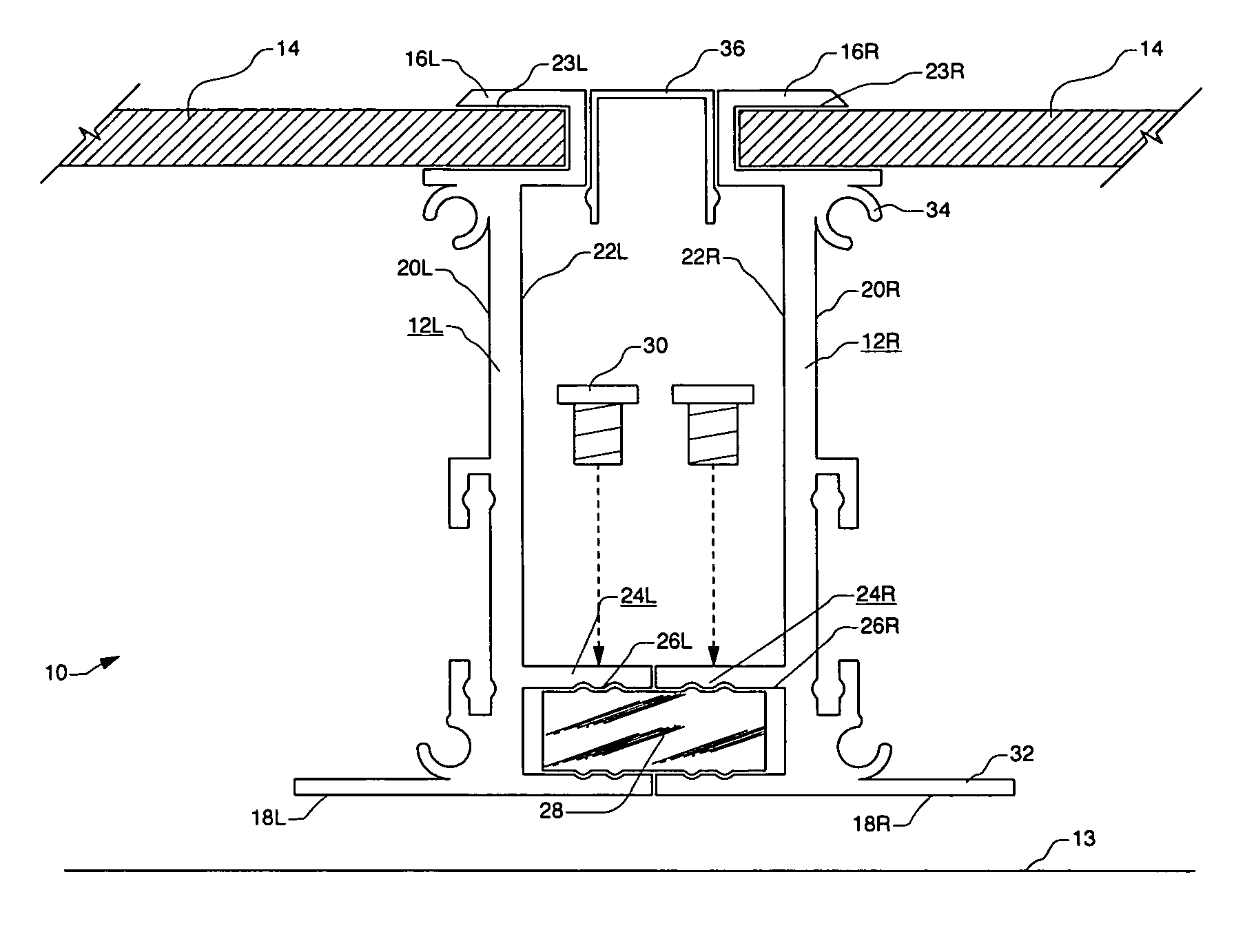
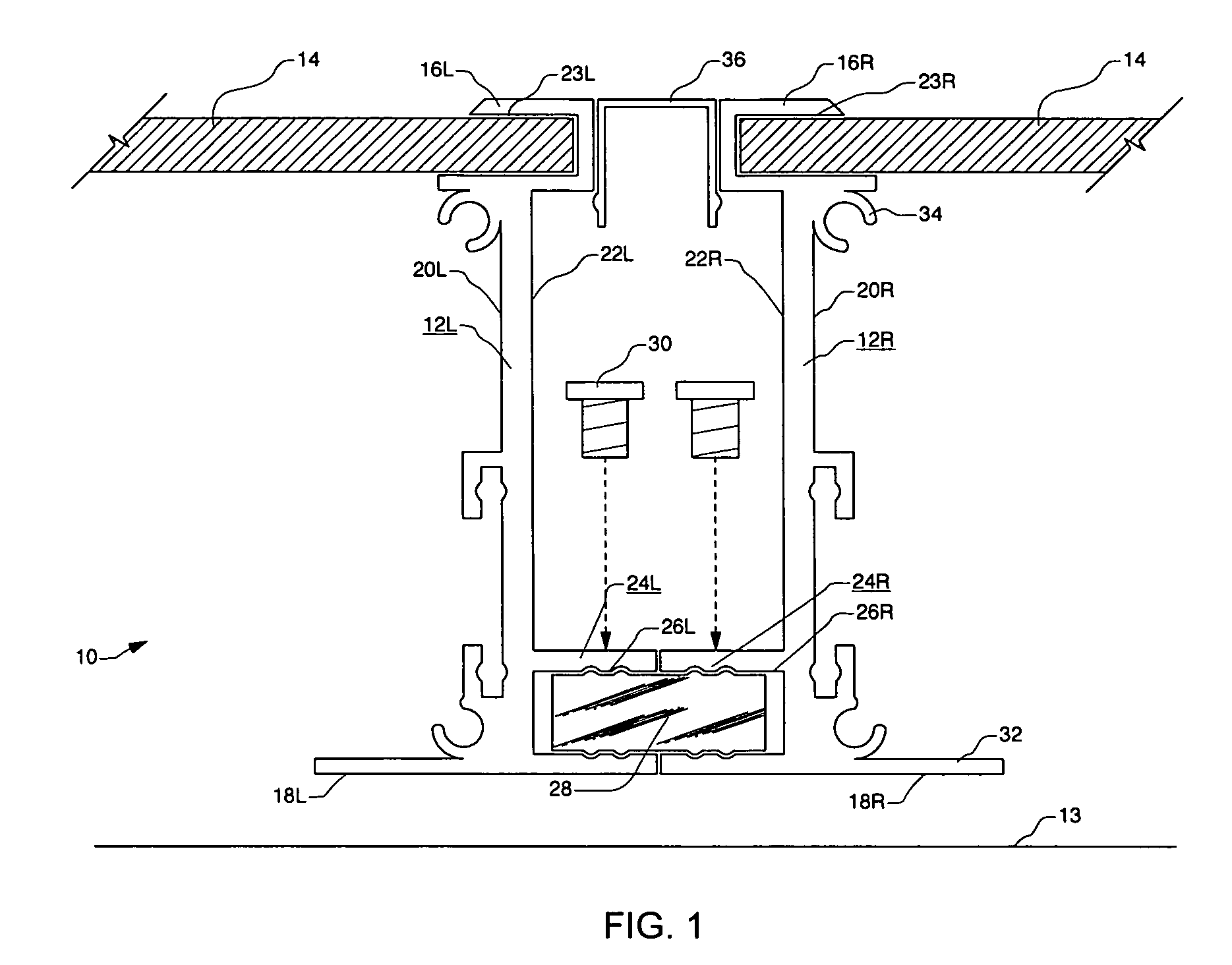
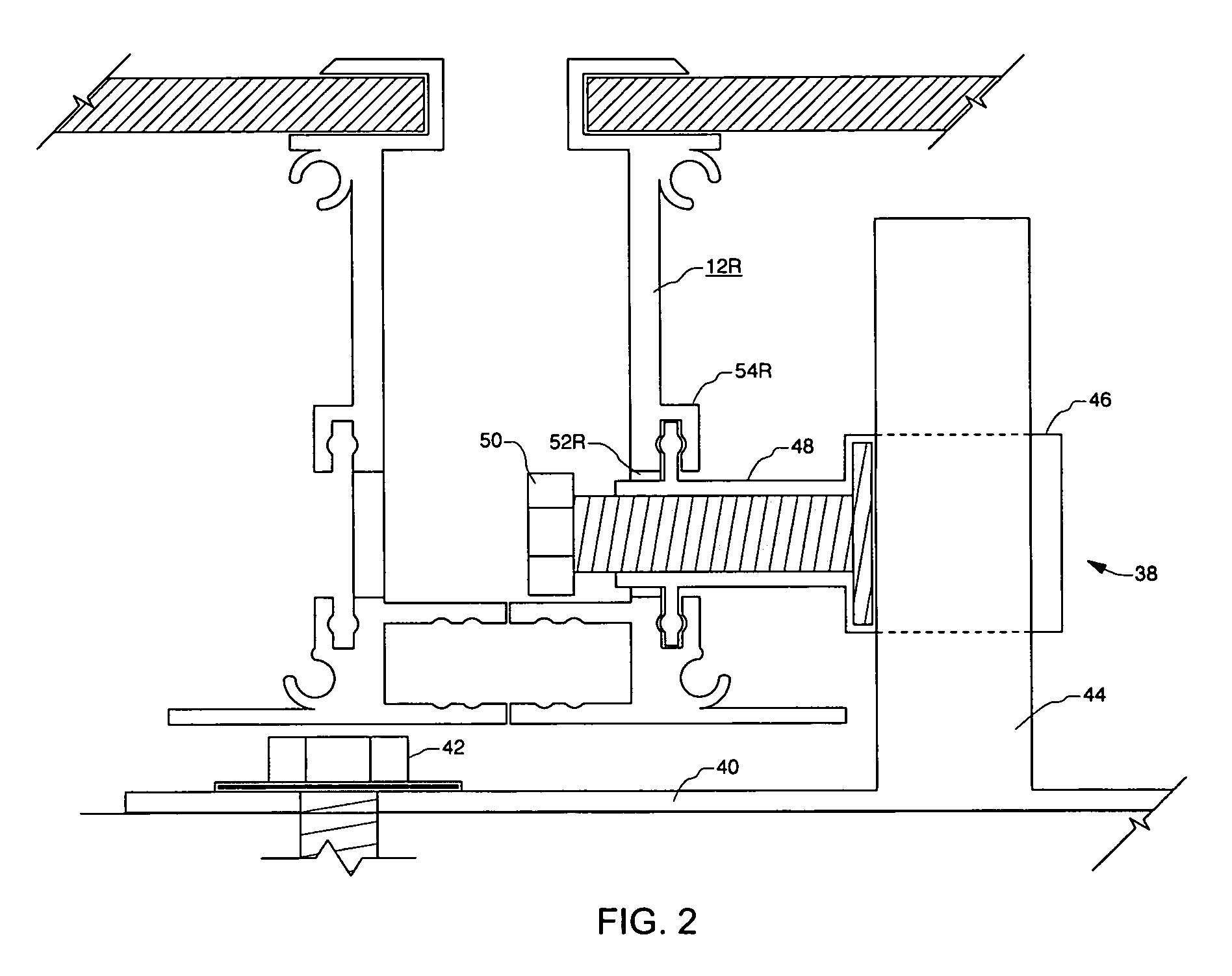
[0060]Referring to FIGS. 1 through 7, wherein like reference numerals refer to like components in the various views, there is illustrated therein a new and improved apparatus for mounting photovoltaic modules to a roof, generally denominated 10 herein.

[0061]FIG. 1 is a side elevation cross-sectional view of a first embodiment of an interlocking photovoltaic module mounting system 10 of this invention, illustrating two adjacent interlocked photovoltaic module frames 12L, 12R above a roof 13. Each frame member encloses the perimeter of a photovoltaic laminate 14. Each frame is made of substantially similar construction on all four sides, and each includes a top portion 16L, 16R, bottom portion 18L, 18R, inside surface 20L, 20R, and outside surface 22L, 22R. Inside surfaces 20L, 20R include a recess 23L, 23R for capture of the laminate 14. The frame member outside surfaces 22L, 22R include at least one interlocking mechanism 24L, 24R for adjoining frame 12L to adjacent frame 12R to for...


PUM


Abstract

An interlocking photovoltaic module mounting system that provides a one piece, integrated photovoltaic module frame portion that is directly mountable to a support structure and interlocks with separate adjoining photovoltaic module frame portions. The apparatus includes a frame member for enclosing the perimeter of a photovoltaic module, having an inside surface and outside surface, with the inside surface including a recess for capture of the panel. The frame member outside surface includes at least one interlocking means for affixation to the complementary outside surface of an adjacent frame-member. The frame member includes a height-adjustable foot portion for supporting the frame member on a roof, so that adjacent frame members may be interlocked to form an array, and the foot portion may be adjusted to level the formed array on the roof.

Description

CROSS REFERENCE TO RELATED APPLICATIONS[0001]The present application claims the benefit of the filing date of U.S. Provisional Patent Application Ser. No. 60 / 542,463, filed 5 Feb. 2004, and U.S. Provisional Patent Application Ser. No. 60 / 568,513, filed May 5, 2004.STATEMENT REGARDING FEDERALLY SPONSORED RESEARCH OR DEVELOPMENT[0002]Not applicable.REFERENCE TO A MICROFICHE APPENDIX[0003]Not applicable.TECHNICAL FIELD[0004]The present invention relates generally to photovoltaic modules and associated frames and mounting hardware, and more particularly to an interlocking photovoltaic module mounting system that provides a one piece, integrated photovoltaic module frame that is directly mountable to a support structure and interlocks with separate adjoining photovoltaic module frames.BACKGROUND INFORMATION AND DISCUSSION OF RELATED ART[0005]Photovoltaic (PV) modules and related mounting hardware are well known and in widespread use. The most common mass-produced PV modules in use today ...

Claims


Application Information

Patent Timeline
Patent Type & Authority Patents(United States)
IPC IPC(8): H02N6/00
CPCF24J2/5211F24J2/5245F24J2/5254F24J2/526F24J2/5262H02S20/23H02S20/00Y02B10/12Y02B10/20Y02E10/47Y02E10/50F24J2002/4669F24S25/61F24S25/632F24S25/20F24S25/65F24S25/67F24S2025/6006Y02B10/10
Inventor WEST, JOHN RAYMOND
Owner TESLA INC
Learn More