

Virtual antenna array
- Summary
- Abstract
- Description
- Claims
- Application Information
AI Technical Summary
Benefits of technology
Problems solved by technology
Method used
Image

Examples
first embodiment
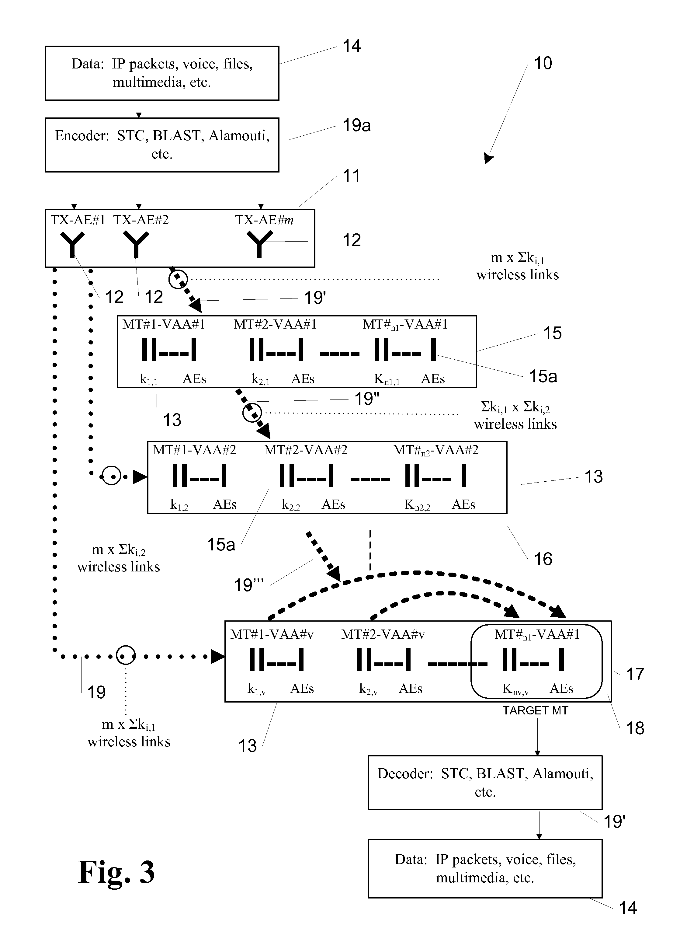
[0080]Referring to FIG. 3 a data communication system is generally identified by reference numeral 10 that comprises a control terminal 11 having m antenna elements 12. The control terminal may be a base station for example. The control terminal 11 is part of a larger network of control terminals (not shown) through which data can be passed. The control terminals serve to divide an area into a number of cells (not shown), as described in the introduction above, permitting inter alia frequency re-use between the cells. There are n1+n2+nv mobile terminals 13 in the cell served by control terminal 11. Referring to FIG. 3A each mobile terminal 13 comprises a RAKE receiver 14a having a plurality of antenna elements 15a, each of which acts as a “finger” that can lock on to uncorrelated copies of the signal created by multipath. The first finger locks on to the strongest signal, the second finger the next strongest and so on. The signal from each finger can be combined by the diversity com...
second embodiment
[0085]Referring to FIG. 4 a data communication system is generally identified by reference numeral 20 that is similar to the data communication system 10 with like numerals indicating like parts. The main difference between the two embodiments is that the data communications system 20 operates in both a downlink and an uplink (mobile terminal to control terminal) mode. One advantage of this is that the power of the t-MT 28 can be reduced leading to less interference in the cell. Another advantage is that whilst the t-MT 28 might be in a fade with respect to the control terminal 21, it is unlikely to be in a fade with respect to the other mobile terminals 13 in the VAAs 25, 26 and 27 such that it can both send and receive data at an improved bit error rate to and from the control terminal 21.
[0086]Referring to FIG. 5 a flowchart showing the main functional requirements of the algorithms required to run a data communication system in the manner described above is generally identified ...
third embodiment
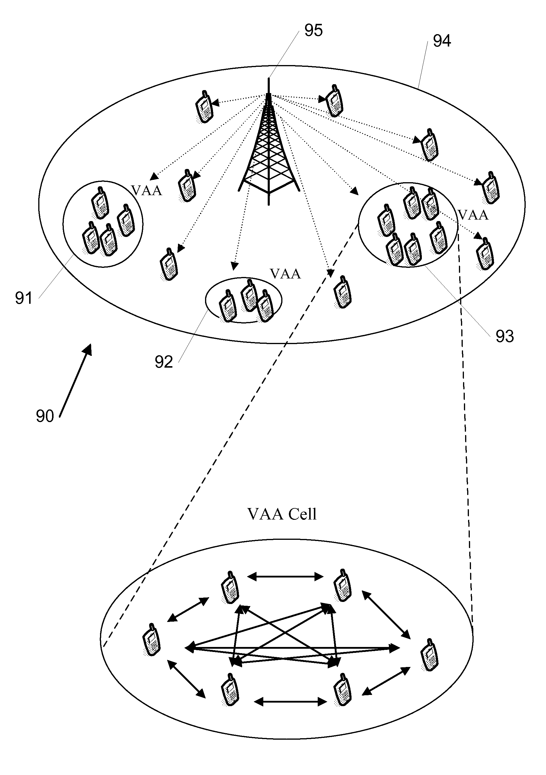
[0144]Referring to FIG. 8 a data communication system is generally identified by reference numeral 60 that comprises a control terminal 61 comprising m antenna elements. There is a plurality of mobile terminals 62 that are part of a VAA 63 that has been set up in accordance with the rules described above. Each mobile terminal 62 is free lo move within the cell served by the control terminal 61. The number of mobile terminals 62 is greater than the number of antenna elements of the control terminal. If a mobile terminal 62 moves out of the cell, another control terminal (not shown) will serve it. Each mobile terminal comprises a plurality of antenna 64. In use, data 65 is received from higher layers of the network at the control terminal 61 and appropriately encoded for the transmission scheme in use. The data 65 is transmitted from the control terminal 61 and the mobile terminals receives it and all bar a t-MT 66 re-transmit the data 65 for the benefit of the target mobile 66. The t...
PUM
 Abstract
Description
Claims
Application Information