
Fabrication method of semiconductor device

a technology of semiconductor devices and fabrication methods, applied in the direction of semiconductor devices, electrical devices, transistors, etc., can solve the problems of not being able to replace the metal layer of the mos transistor, the resistance of doped polysilicon is still too high, and the majority of metals have bad adhesion to silicon oxide, etc., to achieve the effect of enhancing the thermal stability of metal salicid

Active Publication Date: 2009-09-29
UNITED MICROELECTRONICS CORP
View PDF6 Cites 0 Cited by
  • Summary
  • Abstract
  • Description
  • Claims
  • Application Information

AI Technical Summary

Benefits of technology

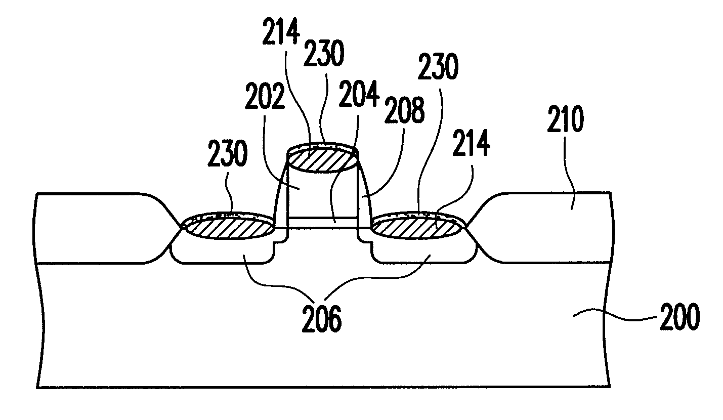
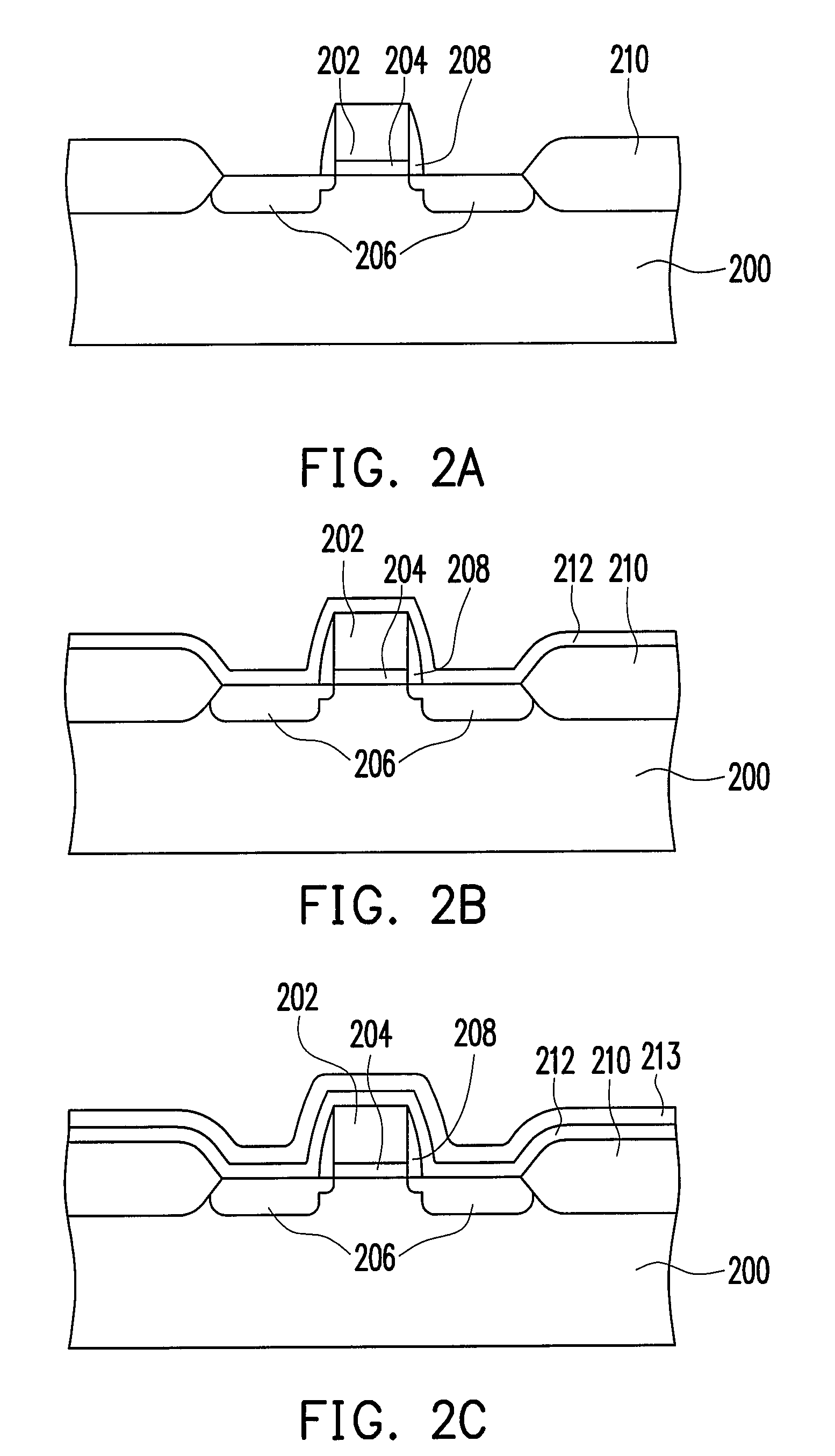
The present invention provides a method of fabricating a semiconductor device using a refractory metal alloy salicide layer that has low resistance, low process temperature, and minor narrow-line-width effect. The method includes steps of forming a silicon-containing conductive layer, adding a refractory metal alloy layer over it, and forming a protection layer over the refractory metal alloy layer. The protection layer prevents damage to the refractory metal alloy layer during the etch process. The refractory metal alloy salicide layer replaces the prior art refractory metal salicide to enhance its thermal stability. The method also includes steps of performing a surface treatment to increase the thickness of the protection layer. The semiconductor device fabricated using this method has improved performance and reliability.

Problems solved by technology

However, most of metals have bad adhesion to silicon oxide.
Even if being doped, resistance of doped polysilicon is still too high, and the doped polysilicon cannot replace the metal layer of the MOS transistor in this aspect.
The thermal stability of nickel salicide, however, is poor.

Method used


Image

  • Fabrication method of semiconductor device
  • Fabrication method of semiconductor device
  • Fabrication method of semiconductor device

Examples


Embodiment Construction

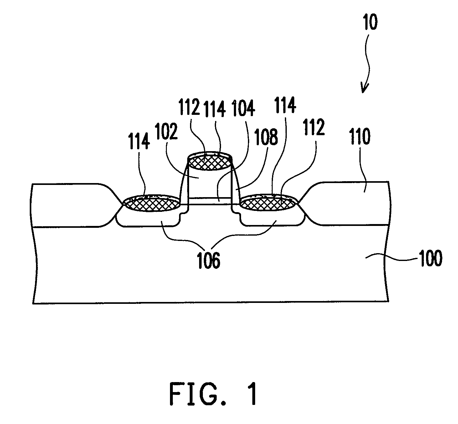
[0032]Following are descriptions of an embodiment of semiconductor device, for example, a metal-oxide-semiconductor (MOS) transistor. The present invention, however, is not limited thereto. The method of the present invention can be applicable to other silicon-containing structures.

[0033]FIG. 1 is a cross sectional view showing a semiconductor device according to an embodiment of the present invention. Referring to FIG. 1, the semiconductor device 10 comprises a silicon substrate 100, a gate 102, a gate oxide layer 104, source / drain regions 106, spacers 108, isolation structures 110, a refractory metal salicide layer 112 and a protection layer 114. The gate 102 and the source / drain regions 106 are called silicon-containing conductive layers. The isolation structures 110 are disposed in the silicon substrate 100 to define an active area. The gate 102, the gate oxide layer 104, the source / drain regions 106, the spacers 108, the refractory metal salicide layer 112 and the protection la...


PUM

PropertyMeasurementUnit
conductiveaaaaaaaaaa
refractoryaaaaaaaaaa
thicknessaaaaaaaaaa

Abstract

A method of fabricating a semiconductor device is provided. The method includes forming a refractory metal alloy layer over a silicon-containing conductive layer. The refractory metal alloy layer is constituted of a first refractory metal and a second refractory metal. Thereafter, a cap layer is formed on the refractory metal alloy layer. A thermal process is performed so that the refractory metal alloy layer reacts with silicon of the silicon-containing conductive layer to form a refractory metal alloy salicide layer. Afterwards, an etch process with an etch solution is performed to removes the cap layer and the refractory metal alloy layer which has not been reacted and to form a protection layer on the refractory metal alloy salicide layer.

Description

CROSS-REFERENCE TO RELATED APPLICATION[0001]This application is a continuation-in-part of a prior application Ser. No. 11 / 160,233, filed on Jun. 15, 2005, which is allowed. The entirety of the above-mentioned patent application is hereby incorporated by reference herein and made a part of specification.BACKGROUND OF THE INVENTION[0002]1. Field of the Invention[0003]The present invention relates to a semiconductor device and a fabrication method thereof, and more particularly to a semiconductor device comprising at least one conductive structure which has a refractory metal salicide layer, and a fabrication method thereof.[0004]2. Description of the Related Art[0005]In semiconductor technology, a metal-oxide-semiconductor (MOS) transistor is composed of three electrodes: a gate, a source and a drain. The early MOS transistor is composed of a metal layer, a silicon oxide layer and a silicon substrate. However, most of metals have bad adhesion to silicon oxide. Polysilicon with good ad...

Claims


Application Information

Patent Timeline
Patent Type & Authority Patents(United States)
IPC IPC(8): H01L21/44
CPCH01L29/665H01L29/7833H01L29/6659
Inventor CHANG, YU-LANHSIEH, CHAO-CHINGCHIANG, YI-YIINGCHEN, YI-WEIHUNG, TZUNG-YU
Owner UNITED MICROELECTRONICS CORP
Learn More