Amplitude controlled quartz oscillator with broad voltage and temperature range

a quartz oscillator and amplitude control technology, applied in the direction of pulse automatic control, predetermined time interval producing apparatus, instruments, etc., can solve the problems of increasing cost and degrading power supply rejection rate, and achieve high transconductance level

Active Publication Date: 2009-10-06
EM MICROELECTRONIC-MARIN
View PDF9 Cites 22 Cited by
  • Summary
  • Abstract
  • Description
  • Claims
  • Application Information

AI Technical Summary

Benefits of technology

[0005]It is one of the main objects of the present invention to overcome the aforementioned drawbacks by providing an oscillator with a high transconductance level without requiring the introduction of any elements that degrade the power supply rejection rate.
[0015]This oscillator allows a high transconductance to be obtained due to the use of two complementary transistors polarised in active operating conditions, while not degrading the power supply rejection rate owing to the use of integrated polarising means for the second active transistor, which further ensures a more reduced necessary surface.
[0017]As the overall object of the oscillator is to provide at output a clock signal at a given frequency, an amplifier for alternating signals is added for this purpose at the input of the circuit forming the core of the oscillator in order to be rid of distortion problems observed at the output. Advantageously, an inverting amplifier is provided at the oscillator input terminal including an inverter formed of two transistors of complementary type, controlled by means of two integrated capacitive input inverting amplifiers each powered by the output of the other capacitive input inverting amplifier and a power supply terminal, respectively the other power supply terminal to prevent a current peak demand when the output is switched.

Problems solved by technology

Nonetheless, this solution requires a considerably higher supply voltage and the use of a high capacitance C in parallel with transistor P2, which powers the two active transistors, which occupies a large surface area on the circuit, and increases the cost thereof while greatly degrading the power supply rejection rate.

Method used


Image

  • Amplitude controlled quartz oscillator with broad voltage and temperature range
  • Amplitude controlled quartz oscillator with broad voltage and temperature range
  • Amplitude controlled quartz oscillator with broad voltage and temperature range

Examples


Embodiment Construction

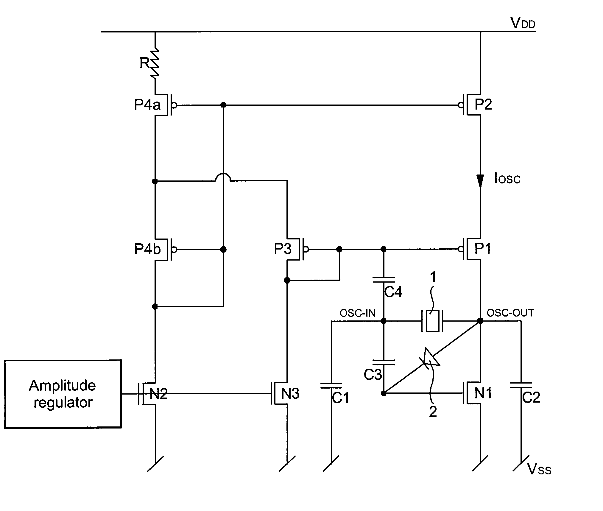
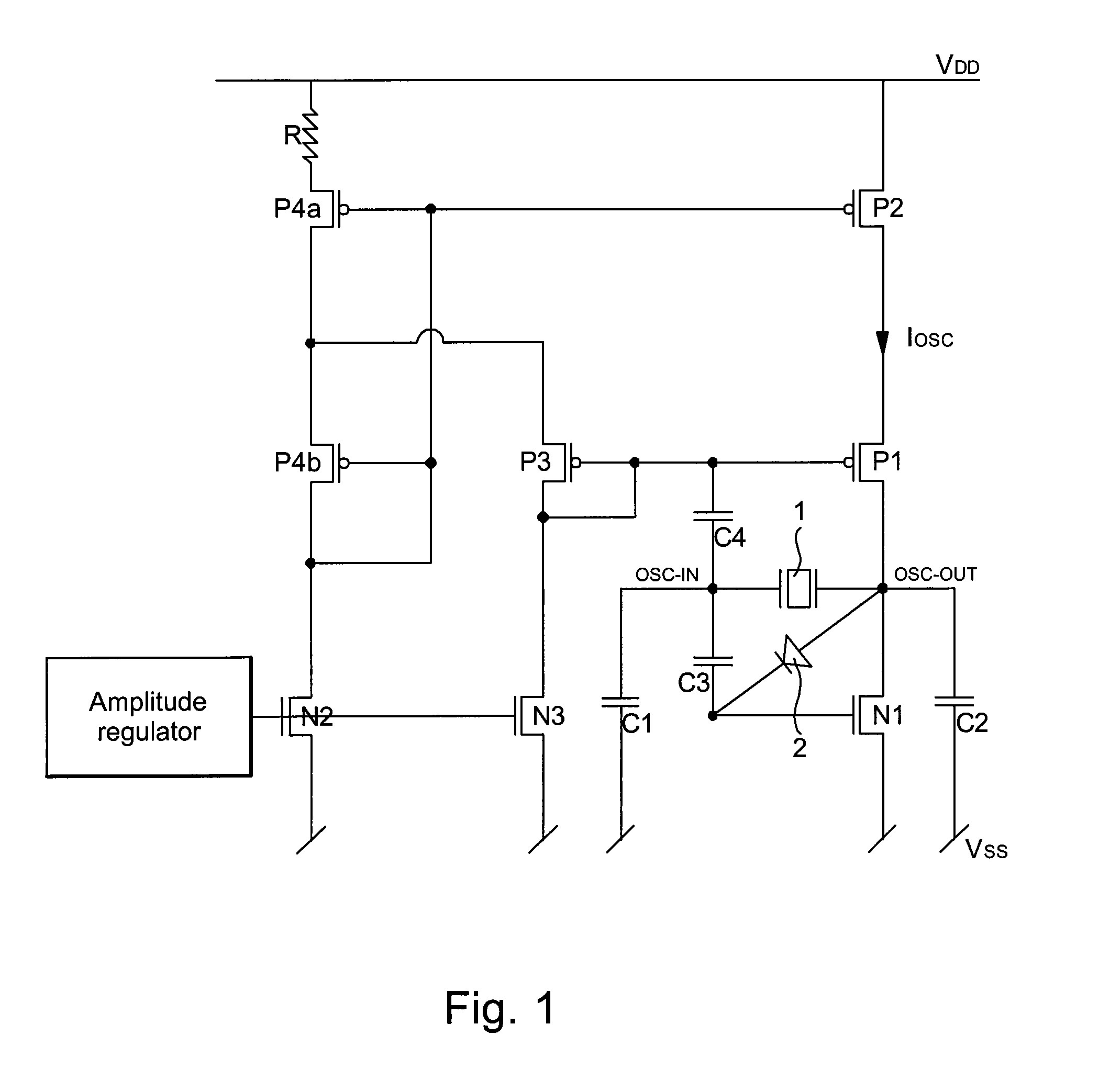
[0028]The present invention, which will now be explained, is given purely by way of non-limiting illustration with reference to FIGS. 1 to 5.

[0029]FIG. 1 shows the oscillator core according to a preferred embodiment of the present invention. The oscillator includes an input terminal (osc_in), an output terminal (osc_out), a resonator 1, and an oscillator circuit, also called the oscillator core. The oscillator circuit is powered via two power supply terminals Vss and Vdd. Two capacitors C1 and C2 are connected between one of the power supply terminals Vss and the input terminal osc_in, respectively the output terminal osc_out, of the oscillator. These indispensable capacitors could be elements connected as indicated, or could be formed by stray capacitances, in particular that of active transistor N1 and connections, connected between power supply terminal Vss and the output terminal osc_out. Polarising means, advantageously formed by a diode connected between the gate of active tra...


PUM


Abstract

The invention concerns an oscillator including an input terminal, an output terminal, a resonator, and an oscillator circuit including: first and second power supply terminals, two capacitors connected between the first power supply terminal and the input terminal, and respectively the output terminal of the oscillator; first and second active transistors of complementary type, forming therewith an inverting amplifier, first and second means for respectively polarizing the first and the second active transistors, a first current source formed by a transistor of the same type as the second active transistor, between the second power supply terminal and the second active transistor, current control means for the second polarizing means, characterized in that in an steady operating conditions, said second polarizing means are arranged for providing a polarization voltage across the gate of the second active transistor corresponding to the transistor gate voltage of the first current source to within one voltage shift.

Description

[0001]This application claims priority from European Patent Application No. 06123107.2, filed Oct. 27, 2006, the entire disclosure of which is incorporated herein by reference.FIELD OF THE INVENTION[0002]The present invention concerns, generally, an oscillator circuit to be used for making a time base for an electronic watch, a portable telephone or any other electronic device requiring such a time base. The present invention concerns, more specifically, an amplitude controlled oscillator circuit.BACKGROUND OF THE INVENTION[0003]There is known from the prior art, in particular from CH Patent No. 580 358, an amplitude controlled quartz oscillator, shown in a simplified manner in FIG. 6. Such amplitude-controlled oscillators are used since they reduce the supply current as soon as the amplitude of the oscillator reaches a reasonable value. The oscillator core consists of an inverting amplifier with the quartz crystal as feedback and load capacitances C1 and C2 for providing the necess...

Claims


Application Information

Patent Timeline
Patent Type & Authority Patents(United States)
IPC IPC(8): H03B5/32
CPCH03B5/04H03B5/364H03B2200/0066H03B2200/0062H03B2200/0038
Inventor NOVAC, PINCHAS
Owner EM MICROELECTRONIC-MARIN
Why Eureka
Try Eureka