Ultrasonic probing method and apparatus therefor utilizing resonance phenomenon

a resonance phenomenon and ultrasonic probe technology, applied in the direction of instruments, specific gravity measurement, processing detected response signals, etc., can solve the problems of large number of measurement steps, individual differences in size, and relative difficulty in probing a flaw in a probe target formed of a material having a large scattering attenuation, so as to improve the accuracy of probing and large scattering attenuation

Inactive Publication Date: 2009-10-13
H&B SYST +2
View PDF19 Cites 9 Cited by
  • Summary
  • Abstract
  • Description
  • Claims
  • Application Information

AI Technical Summary

Benefits of technology

[0011]The present invention has an object of providing an ultrasonic probing method and apparatus, by which a wide band ultrasonic wave (ultrasonic wave with a wide band; including a low frequency range) is input to a probing target by a transmission probe, and a wide band ultrasonic wave is received by a receiving probe; a narrow band spectrum of a specified frequency range is extracted from the received wide band wave, so that even a flaw causing a large scattering attenuation can be probed; the sizing coefficients are set for performing the probing with a high precision, and by setting the sizing coefficients to appropriate values, the waves other than the probing target waves are removed or reduced, so that the individual difference in the sizing result due to the ability of the measuring personnel can be eliminated to improve the precision of the probing; a flaw with a long probing length can be probed; and thus the number of probing steps can be significantly reduced from the conventional art.Means for Solving the Problems

Problems solved by technology

1) According to the conventional methods, a high frequency vibration is used. Therefore, it is relatively difficult to probe a flaw in a probing target formed of a material having a large scattering attenuation such as cast iron or the like.
2) According to the conventional methods, probing is easily performed when a probing area is limited, for example, when a flaw in a welded section is to be probed. However, when a probing area is large, the ultrasonic wave transmission and receiving probes need to be moved for scanning in the entire probing area to each measurement point. This requires a huge number of measurement steps.
3) According to the conventional methods, when it is found whether there is a flaw or not, the determination on the sizing (detection of the width, height, size and the like of the flaw) relies on the ability of the measuring personnel. For this reason, individual differences are generated in sizing.
4) According to the conventional methods, a high frequency vibration is used. Therefore, the amount of vibration attenuated and lost inside the probing target is large. Although being effective for probing a flaw with a short probing length of about 100 mm, the methods are not usable to probe a defect (flaw) located at a long probing length.

Method used


Image

  • Ultrasonic probing method and apparatus therefor utilizing resonance phenomenon
  • Ultrasonic probing method and apparatus therefor utilizing resonance phenomenon
  • Ultrasonic probing method and apparatus therefor utilizing resonance phenomenon

Examples


example 1

[0207]With reference to FIG. 6 through FIG. 17, Example 1 in which a longitudinal 12th-order resonant spectrum of nB·f1 frequency=1420 kHz is sampled out and the component wave is compared at measurement points will be described.

[0208]FIG. 6 shows a measurement model of the probing target 30. The measurement model has a planar size of length X=120 mm and width Y=120 mm, and a thickness W=25 mm, and is formed of stainless steel. A line-like flaw Z is made as shown in the figure.

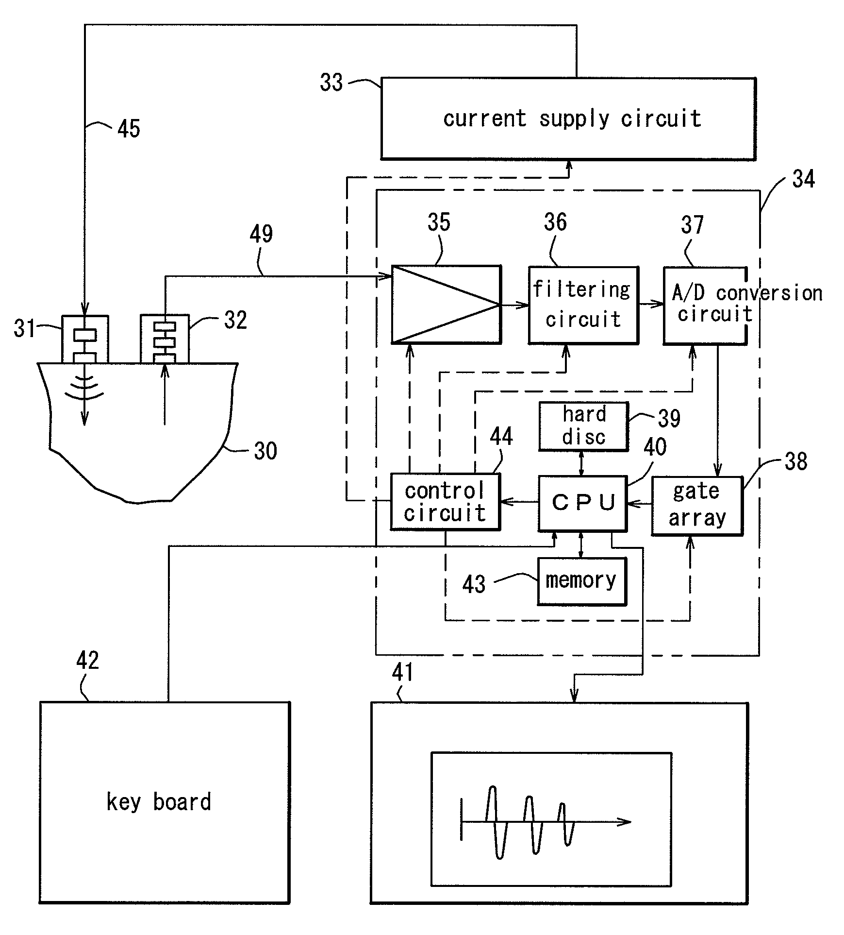
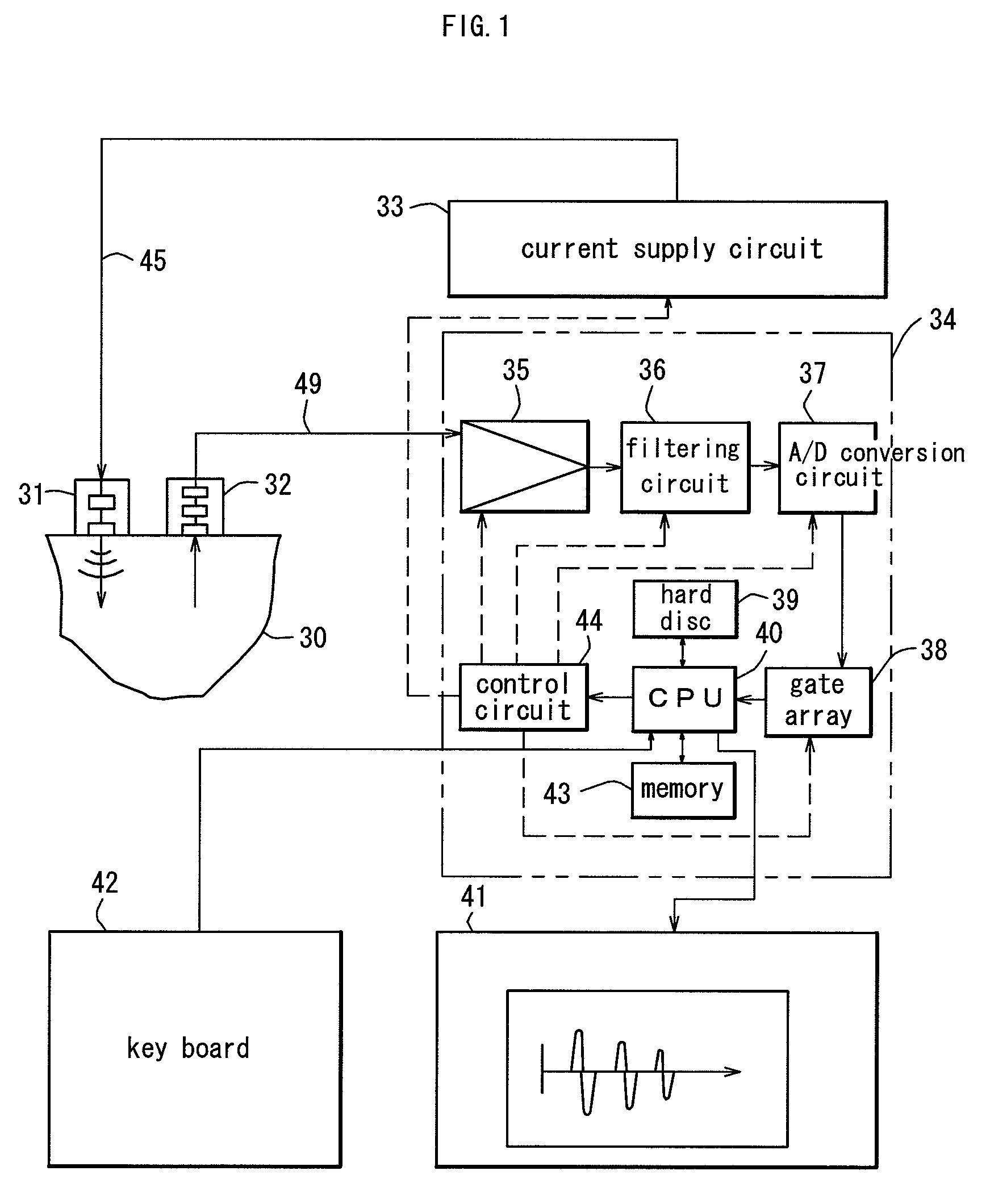
[0209]The transmission probe 31 and the receiving probe 32 respectively including the vibrators 47 and 52 (see FIG. 2 and FIG. 4) each having a diameter of 15 mmφ are located, such that the distance “a” between the centers of the probes 31 and 32 is fixed at 90 mm and a line segment connecting the probes 31 and 32 is perpendicular to the flaw Z. The line segment is translated by an interval of a moving amount ΔX=9 mm. Thus, a multi-point measurement, by which a plurality of received waves Gj(t) are measured an...

example 2

[0248]With reference to FIG. 18 through FIG. 26, Example 2 in which a transverse 8th-order resonant spectrum of nB·f1 frequency=664 kHz is sampled out and the component wave is compared at measurement points will be described.

[0249]FIG. 18 shows a measurement model of the probing target 30. The measurement model has a planar size of length X=300 mm and width Y=400 mm, and a thickness W=20 mm, and is formed of stainless steel. A line-like flaw Z is made as shown in the figure. The width of the flaw Z is ε1=18 mm.

[0250]The transmission probe 31 including the vibrator 47 (see FIG. 2) having a diameter of 15 mmφ is located at a fixed position. A receiving probe 32 is located on a circumference having a constant radius R=160 mm and having the central point of the transmission probe 31 as the center. (The radius of the circumference corresponds to the distance “a” between the centers of the transmission probe 31 and the receiving probe 32.) The receiving probe 32 is moved in the circumfer...

example 3

[0284]With reference to FIG. 27 through FIG. 41, Example 3 in which a flaw is probed inside cast iron having an especially large scattering attenuation will be described.

[0285]In Example 1, the measurement is performed on a stainless steel probing target having a thickness W of 25 mm. A longitudinal 12th-order resonant spectrum of 1420 kHz (nB·fS1=12×118.4=1420 kHz) is sampled out by an arithmetic operation or band pass filtering, and the obtained component wave GAj(t) at measurement points is provided for a comparative display (see FIG. 14).

[0286]In Example 2, the measurement is performed on a stainless steel probing target having a thickness W of 20 mm. A transverse 8th-order resonant spectrum of 664 kHz (nB·fS1=8×83=664 kHz) is sampled out by an arithmetic operation or band pass filtering, and the obtained component wave GAj(t) at measurement points is provided for a comparative display. In both of Examples 1 and 2, analysis is performed in a relatively high frequency band.

[0287]...


PUM

PropertyMeasurementUnit
frequencyaaaaaaaaaa
frequencyaaaaaaaaaa
frequencyaaaaaaaaaa

Abstract

A flaw Z with a long probing length inside a probing target is allowed to be probed. The waves other than the probing target waves are removed or reduced, so that the individual difference in the sizing result due to the ability of the measuring personnel is eliminated to improve the precision of the probing. A transmission probe 31 and a receiving probe 32 for transmitting and receiving a wide band ultrasonic wave are included. Each time the positions of the probes 31 and 32 are moved, a received wave Gj(t) is obtained. From a spectrum Fj(f) corresponding to the received wave Gj(t), a narrowband spectrum FAj(f) is extracted. A component wave GAj(t) corresponding to the narrow band spectrum FAj(f) is obtained by inverse Fourier transformation. The component wave GAj(t) is provided for a comparative display using a predetermined sizing coefficient. The position of a flaw Z is determined inside a probing target 30 right below the line segment connecting the centers of the transmission probe 31 and the receiving probe 32, based on at which of the measurement points a wave is generated on the comparative display screen.

Description

TECHNICAL FIELD[0001]The present invention relates to an ultrasonic probing method and an apparatus there for utilizing a resonance phenomenon, by which presence / absence of a flaw inside a metal device formed of stainless steel, inconel (nickel-based corrosion resistant and heat-resistant alloy containing chrome and iron), cast iron or the like or in a nuclear reactor pipe, a turbine blade or the like, or a flaw in a welded section of an architecture or construction structure of steel is checked by probing, or sizing of such a flaw is performed by probing.BACKGROUND ART[0002]According to a conventional ultrasonic probing method (see patent document 1), a flaw in a probing target, for example, a steel material, is probed as follows. A narrowband wave having a high frequency of 1.0 MHz, 1.5 MHz or 2.0 MHz is input to a surface of the steel material in an oblique direction into a position right below the surface using an oblique probe usable both for transmission and receiving. Based o...

Claims


Application Information

Patent Timeline
Patent Type & Authority Patents(United States)
IPC IPC(8): G01N29/12G01N29/26
CPCG01N29/069G01N29/11G01N29/265G01N29/46G01N29/348G01N2291/102G01N2291/044
Inventor HIROSE, MASAYUKIKAMEYAMA, MASASHIDOHI, NOBUKIOKUMURA, MITSUOZHANG, HONG
Owner H&B SYST
Why Eureka
Try Eureka