Hybrid vacuum system for fuel deoxygenation

a vacuum system and fuel deoxygenation technology, applied in the field of vacuum system, can solve the problems of increasing the size increasing the cost and overall weight, and affecting the overall configuration and operation of the vacuum pump, so as to reduce the volume flow through the vacuum pump

Active Publication Date: 2009-10-13
RTX CORP
View PDF10 Cites 14 Cited by
  • Summary
  • Abstract
  • Description
  • Claims
  • Application Information

AI Technical Summary

Benefits of technology

[0008]The ejector creates a first vacuum for the first vacuum stage and the second vacuum stage. The vacuum pump assists the ejector for the second vacuum stage only, to create a second vacuum. The discharge from the second vacuum stage is all that passes through the vacuum pump reducing the volume flow through the vacuum pump.

Problems solved by technology

As the size of vacuum pumps increase so does the cost and overall weight.
As can be appreciated, space aboard an aircraft is limited and any increase in device size affects overall configuration and operation.

Method used


Image

  • Hybrid vacuum system for fuel deoxygenation
  • Hybrid vacuum system for fuel deoxygenation
  • Hybrid vacuum system for fuel deoxygenation

Examples


Embodiment Construction

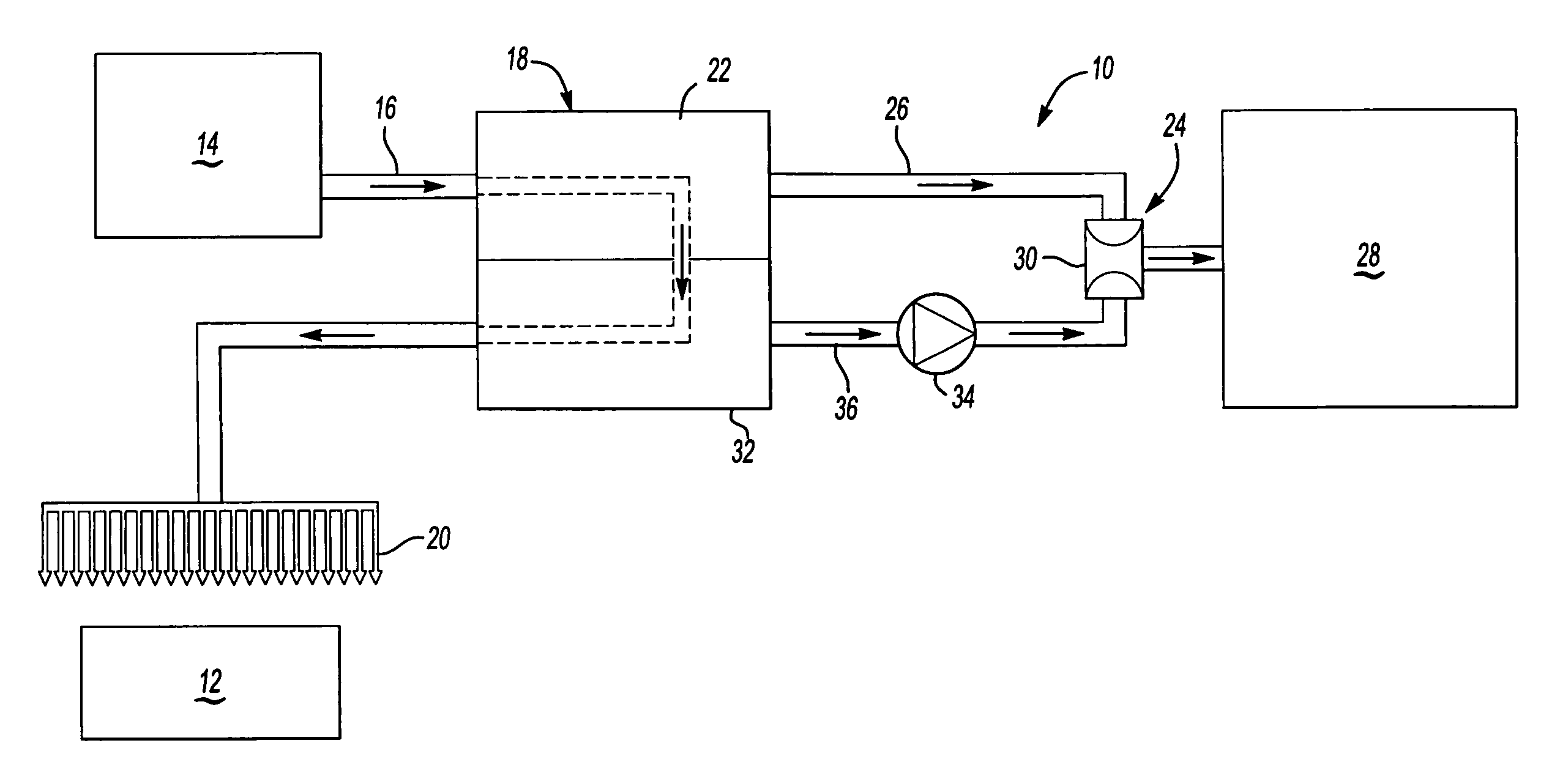
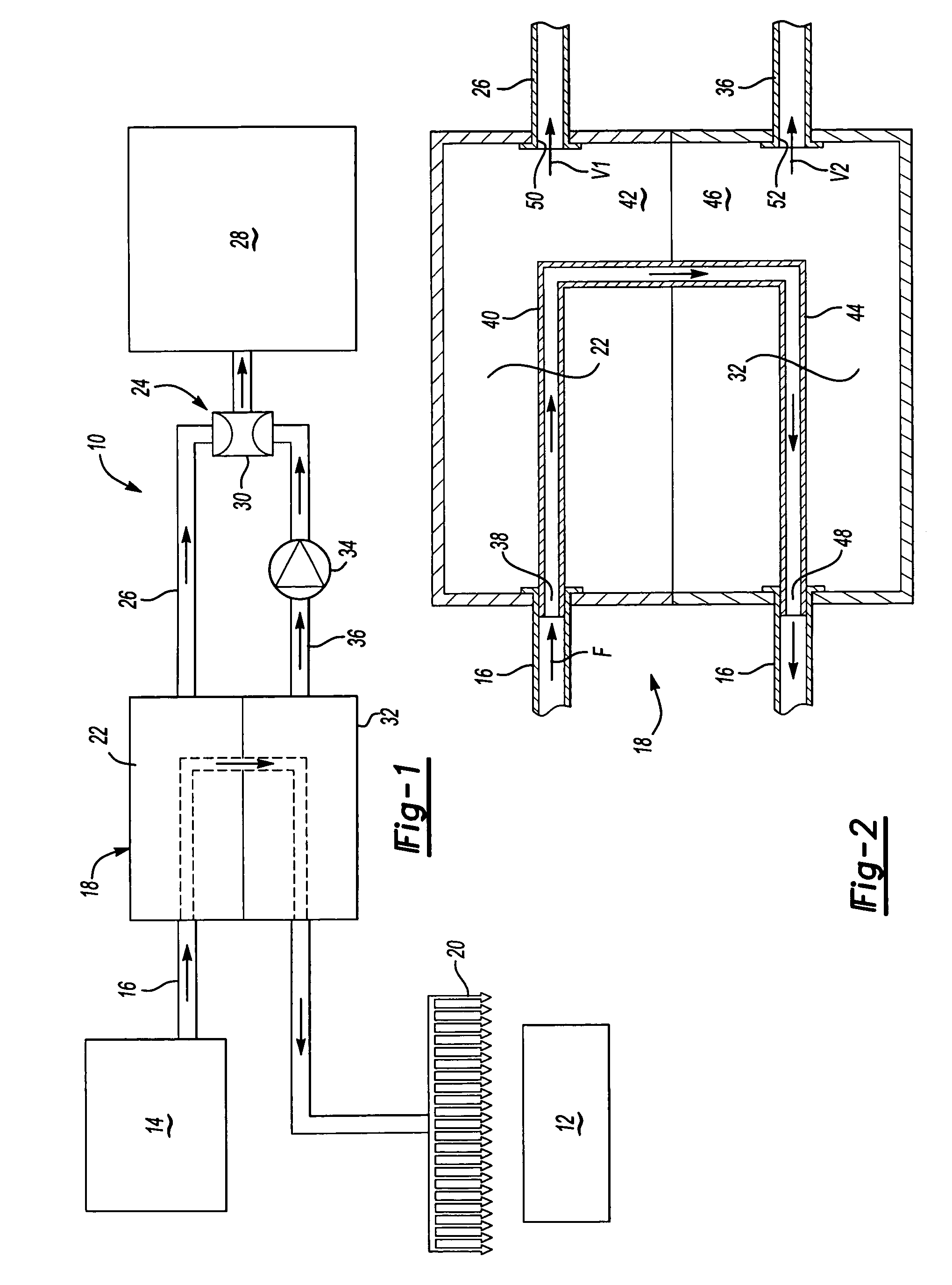
[0013]A fuel delivery system 10 is shown schematically in FIG. 1. The system 10 is preferably for use in delivering fuel to a gas turbine engine 12. Fuel from a fuel supply 14 flows through a fuel path 16 to a fuel stabilization unit (FSU) 18 for de-oxygentating the fuel. The fuel continues to flow through the fuel path 16 exiting the FSU 18 and is discharged from fuel nozzles 20 into the engine 12.

[0014]The FSU 18 removes oxygen and other constituents (such as nitrogen and light hydrocarbons) from the fuel. Within the FSU 18 the fuel flow path 16 passes a first vacuum stage 22. A vacuum pressure within the first vacuum stage 22 is preferably created by an ejector 24. A vacuum stream from the first vacuum stage 22 includes the discharge from the fuel as a result of the deoxygenating process. The vacuum stream exits the FSU 18 and flows through a first vacuum line 26 to the ejector 24 that is creating the vacuum. The vacuum stream from the ejector 24 then flows into a sink 28 or othe...


PUM


Abstract

A fuel system for a gas turbine engine removes oxygen from fuel with a fuel stabilization unit (FSU). The FSU includes a first vacuum stage, where vacuum pressure is created by an ejector and a second vacuum stage where vacuum pressure is created by the ejector and a vacuum pump. The vacuum stream from the first vacuum stage and the second vacuum stage flow through the ejector. The vacuum stream from the second vacuum stage is all that passes through the vacuum pump.

Description

BACKGROUND OF THE INVENTION[0001]This invention relates to a vacuum system for a fuel stabilization unit (FSU) for a gas turbine engine. More particularly, this invention relates to a system for generating a vacuum utilized in removing dissolved oxygen from a fuel stream.[0002]A fuel stabilization unit (FSU) reduces the amount of oxygen dissolved within fuel for a gas turbine engine to increase the maximum allowable temperature of the fuel. One method of removing dissolved oxygen from fuels is by using a semi-permeable membrane de-oxygenator. In a membrane de-oxygenator, fuel is pumped over an oxygen permeable membrane. As the fuel passes over the membrane, a partial oxygen pressure differential across the membrane promotes the transport of oxygen out of the fuel through the membrane.[0003]A vacuum is one means of generating the required partial oxygen pressure differential. Typically, multi-stage vacuums are created using vacuum pumps. Each vacuum pump is sized based on the volume ...

Claims


Application Information

Patent Timeline
Patent Type & Authority Patents(United States)
IPC IPC(8): B01D53/22
CPCB01D19/0036
Inventor REEVE, HAYDEN M.TILLMAN, THOMAS G.
Owner RTX CORP
Why Eureka
Try Eureka