Transition structures and catalytic reaction pathways for the production of hydrogen and oxygen

a transition structure and catalytic reaction technology, applied in the production of electrolytic organics, instruments, energy-based chemical/physical/physical-chemical processes, etc., can solve the problems of high material and maintenance costs of systems employing catalysts, lack of gas purity in the gas separation process, and hydrogen volatilization, etc., to achieve fast dissociation of water molecules, lower cost, and high purity

Inactive Publication Date: 2009-10-13
COASTAL HYDROGEN ENERGY
View PDF6 Cites 6 Cited by
  • Summary
  • Abstract
  • Description
  • Claims
  • Application Information

AI Technical Summary

Benefits of technology

[0006]The present invention provides systems and methods for the ultra fast dissociation of the water molecule at relatively low temperatures, and at higher purity. The present invention further provides for the use of lower cost, near infrared light sources can be used dissociate the water molecule, and radiolysis techniques which can be used to further increase dissociation efficiency and gas purity.
[0008]In a second aspect of the invention, a photolysis cell is presented which is operable to dissociate water molecules into H.sub.2 and O.sub.2 gas. The photolysis cell includes one or more photolysis bottles, each photolysis bottle having an inlet configured to receive water molecules, an H.sub.2 outlet configured to output H.sub.2 gas, and a O.sub.2 outlet configured to output O.sub.2 gas. Each photolysis bottle further includes an undulated bottle wall defining an interior region of the photolysis bottle, and an optically reflective coating disposed on the undulated bottle wall. The deposited optically reflective coating operates to reflect light back within the interior region of the photolysis bottle, and to effectively reduce the wavelength of the light reflected therefrom.

Problems solved by technology

Problems involved in these prior art systems have included volatility of hydrogen when obtained from superheated steam, excessive costs in systems using ultraviolet light sources, material and maintenance costs of systems employing catalysts, and the lack of gas purity in the gas separation process.

Method used


Image

  • Transition structures and catalytic reaction pathways for the production of hydrogen and oxygen
  • Transition structures and catalytic reaction pathways for the production of hydrogen and oxygen
  • Transition structures and catalytic reaction pathways for the production of hydrogen and oxygen

Examples


second embodiment

[0040]The bottle 210 further includes an RF port 242 located on or near the wall's outer surface 215, the RF port being configured to electromagnetically couple an RF (radio frequency) signal of predefined frequency(ies) into the interior region 217. In one embodiment, the frequency(ies) of the supplied RF signal is selected to substantially match the absorption frequency(ies) of the acidic water vapor molecule so as to inhibit recombination of the H.sub.2 and O.sub.2 molecules after dissociation. In a second embodiment, the amplitude and frequency of the RF signal is selected so as to bombard the H.sub.2 and O.sub.2 constituents with ionizing radiation, thereby maintaining their present dissociated state. The RF port 242 may comprise any conventional structure operable to launch the desired RF frequency(ies) signal into the interior region 217, such structures including a TEM (transverse electromagnetic) structure such as coaxial cable, or TE (transverse electric) or TM (transverse...

embodiment 300

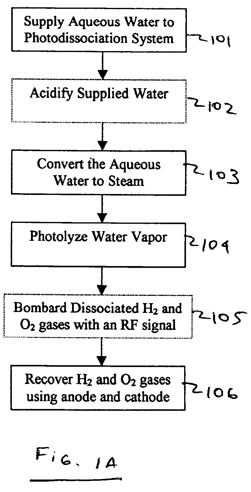
[0045]FIG. 5 illustrates an embodiment 300 of a method for dissociation of water molecules in accordance with one embodiment of the present invention. Initially at 302, water is supplied to a reaction vessel, an embodiment of which is shown and described in FIG. 6 below. The supplied water may be from any source, such as a well, a lake, or an ocean as will be described further below. The interior of the reaction vessel has previously been coated with at least one transition metal oxide photo catalyst. Next at 304 and 306, the water is excited and heated by use of RF microwave radiation from a radiolysis apparatus and ultra violet radiation emitted from a photolysis apparatus. The RF microwave radiation is provided by a variable voltage controlled oscillator and a wave guide emitter at a power range of 0.5-5 watts and frequencies of 20 to 25 GHz. The excited water molecules are heated into water vapor. The heated water vapor molecules then separate into H.sub.2 and O.sub.2 molecules,...
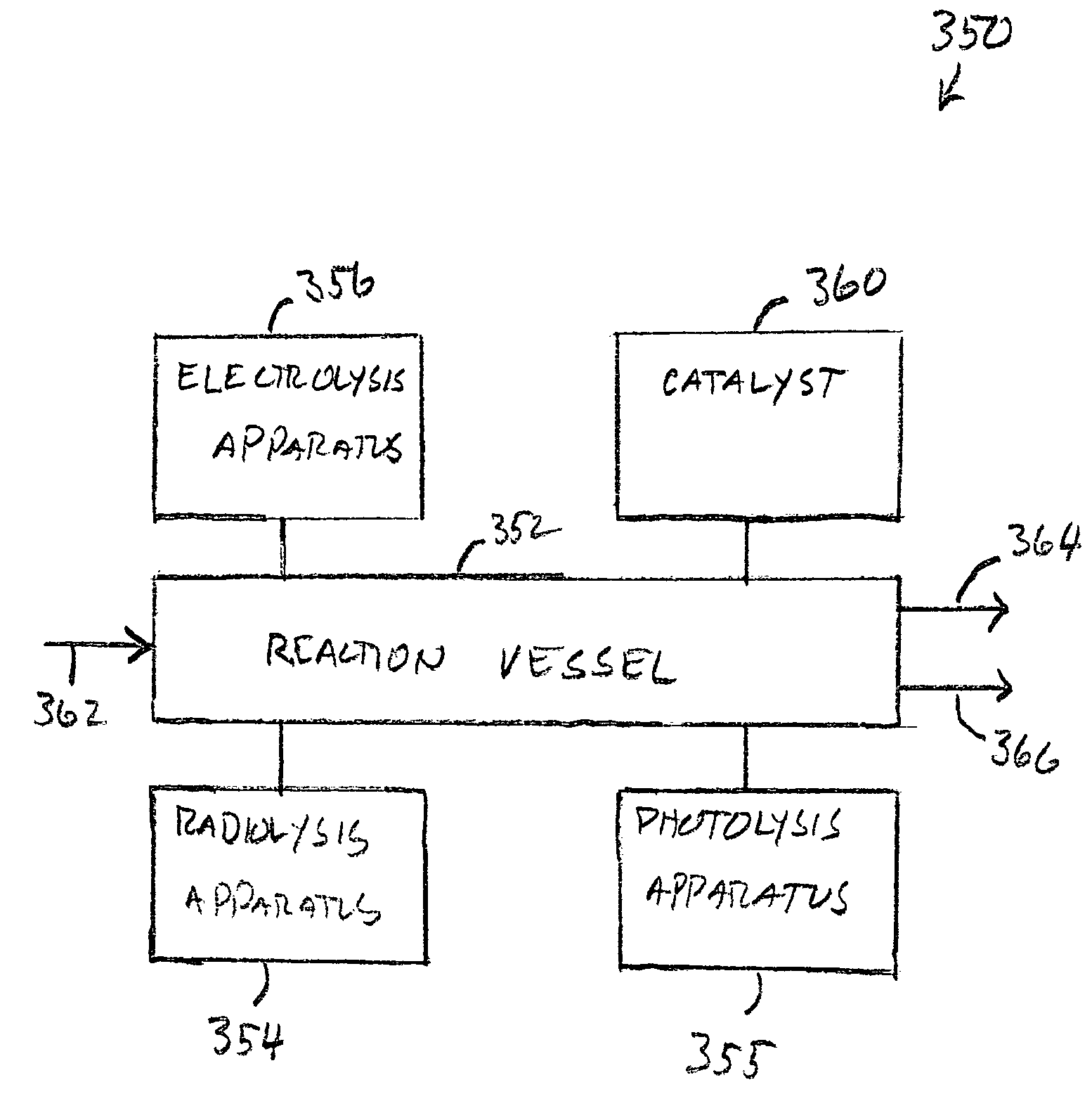
embodiment 350

[0046]FIG. 6 shows a simplified block diagram of an embodiment 350 of a dissociation system employing the method illustrated in FIG. 5. The exemplary system illustrates a reaction vessel 352 having an inlet 362 for water, an oxygen outlet 364 and a hydrogen outlet 366, at least one radiolysis mechanism 354, such as RF emitter apparatus in communication with reaction vessel 352, at least one photolysis apparatus 355 in communication with said reaction vessel to inject light into the vessel, at least one electrolysis apparatus 356 in communication with reaction vessel 352 to effect cathode anode migration for the respective gases (oxygen and hydrogen) to exit the vessel, and at least one catalyst 360 located within the interior 358 of said reaction vessel 352.

[0047]Initially in the process, the interior surface of reaction vessel 352 is coated with a transition metal oxide catalyst 370. The transition metal oxide catalyst can be taken from the group selected consisting of titanium dio...


PUM

PropertyMeasurementUnit
wavelengthsaaaaaaaaaa

Abstract

The present invention provides a system and method for the dissociation of water into H.sub.2 and O.sub.2 gas. The system and method disclose a reaction vessel having at least one radiolysis apparatus, at least one photolysis apparatus, and at least one electrolysis apparatus, all in communication with said reaction vessel. The reaction vessel has a body, a first end and a second end defining an interior. Further, the reaction vessel has an inlet for receiving water from a water supply into its interior and at least two outlet ports to allows H.sub.2 or O.sub.2 to egress therefrom. Still further, at least one catalyst is located within the interior of the reaction vessel. The radiolysis apparatus, photolysis apparatus, and electrolysis apparatus, in combination the with the catalyst provides for the dissociation of water into H.sub.2 and O.sub.2.

Description

CROSS-REFERENCE TO RELATED APPLICATION(S)[0001]The present continuation-in-part application is related to, and claims priority from, U.S. Ser. No. 60 / 544,907 filed Feb. 13, 2004 and is a continuation-in-part of U.S. Ser. No. 10 / 448,779 filed May 29, 2003, now issued U.S. Pat. No. 7,125,480 B2, which is a continuation-in-part of U.S. Ser. No. 10 / 065,429 filed Oct. 16, 2002 now issued as U.S. Pat. No. 6,669,827 B2, which is a continuation-in-part of U.S. Ser. No. 09 / 883,169 filed Jun. 18, 2001, abandoned and incorporates said applications by reference into this document as if fully set out at this point.FIELD OF THE INVENTION[0002]The present invention generally relates to the production of hydrogen and oxygen. More particular, the present invention relates to the production of hydrogen and oxygen through an apparatus and method for the dissociation of water into its constituent elements of hydrogen and oxygen which utilizes transition structures and catalytic reaction pathways.RELATE...

Claims


Application Information

Patent Timeline
Patent Type & Authority Patents(United States)
IPC IPC(8): B01J19/08C25B1/00C25B1/04
CPCC25B1/003C25B1/04Y02E60/368C25B1/55Y02E60/36
Inventor AUSTIN, GARY NIN
Owner COASTAL HYDROGEN ENERGY
Why Eureka
Try Eureka