Fully clamped coupled inductors in power conversion circuits

a technology of power conversion circuit and inductor, which is applied in the direction of dc circuit to reduce harmonics/ripples, electric variable regulation, instruments, etc., can solve the problems of increasing the leakage inductance in these circuits, reducing reducing the size and cost of power converter circuits. , to achieve the effect of improving the electromagnetic compatibility reducing the size and cost of power converter circuits,

Inactive Publication Date: 2009-10-20
WITTENBREDER JR ERNEST HENRY
View PDF9 Cites 62 Cited by
  • Summary
  • Abstract
  • Description
  • Claims
  • Application Information

AI Technical Summary

Benefits of technology

[0009]An object of the subject invention is to reveal a methodology for improving the electromagnetic compatibility of power converter circuits.
[0010]Another object of the subject invention is to reveal a methodology to reduce the size and cost of power converter circuits by making use of parasitic circuit elements that previously provided only a liability.
[0011]Another object of the subject invention is to reveal practical new power conversion circuits with lower comp

Problems solved by technology

The leakage inductance is to a large extent a controllable quantity, but it can never be entirely eliminated.
For all the cases in which the circuit cannot function without magnetic coupling, leakage inductance is, generally, a detriment.
In the circuits that rely on leakage inductance for an efficiency benefit the leakage inductance must be significantly increased to fully realize the benefit claimed, but increasing the leakage inductance in these circuits generally increases overshoot and ringing, which is related to the interaction of the leakage inductance and the circuit's capacitive parasitic circuit elements.
In general, increasing the leakage inductance in circuits that are unworkable without mutual inductanc

Method used


Image

  • Fully clamped coupled inductors in power conversion circuits
  • Fully clamped coupled inductors in power conversion circuits
  • Fully clamped coupled inductors in power conversion circuits

Examples


Embodiment Construction

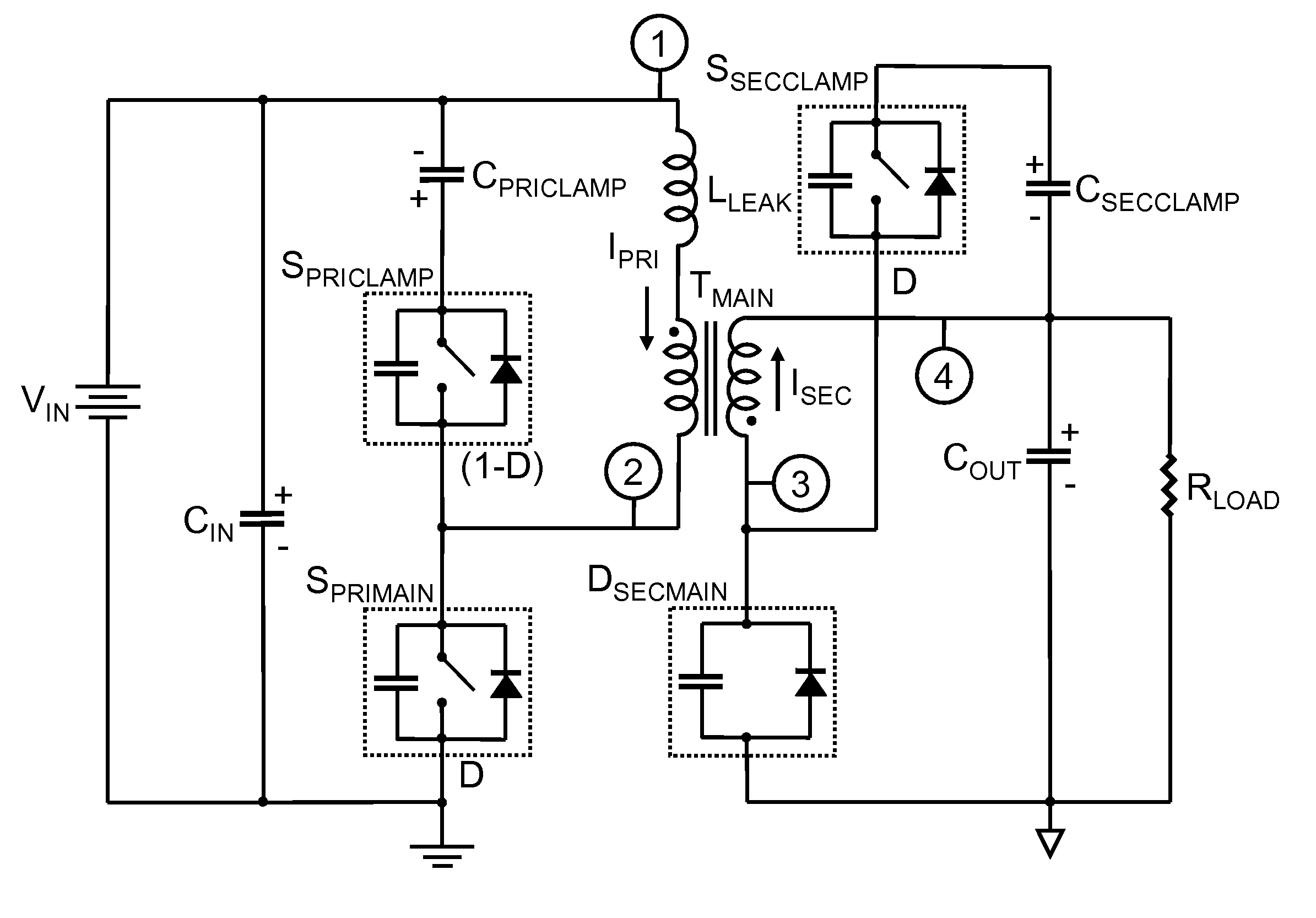
[0076]FIG. 8 illustrates the FIG. 3 circuit with the addition of an improvement, which is the subject of this invention. The improvement consists of an active clamp network comprising an active clamp switch SSECCLAMP and a capacitor CSECCLAMP.

[0077]In FIG. 8 a voltage source VIN has a first terminal connected to a first terminal of an input capacitor CIN, to a first terminal of a clamp capacitor CPRICLAMP, and to a first terminal of a primary winding of a flyback transformer TMAIN. A second terminal of the voltage source VIN is connected to a second terminal of the input capacitor CIN and to a first terminal of a switch SPRIMAIN. A second terminal of the switch SPRIMAIN is connected to a first terminal of a switch SPRICLAMP and to a second terminal of the primary winding of the transformer TMAIN. FIG. 8 illustrates a leakage inductance LLEAK connected in series with the primary winding of the transformer TMAIN, but it should be understood that LLEAK is an inherent part of TMAIN and ...


PUM


Abstract

The subject invention reveals improvement methods for circuits that use a coupled inductor wherein overshoot and ringing associated with leakage inductance of said coupled inductor is entirely eliminated by addition of non-dissipative active clamp networks that clamp each winding during each operating state of a power supply containing said coupled inductor. A further improvement applicable to zero voltage switching circuits that employ an inductor for driving a zero voltage turn on switching transition of a switch enables elimination of said inductor and preserves said zero voltage switching properties by adding leakage inductance to a coupled inductor without any adverse overshoot and ringing effects associated with said leakage inductance. The subject invention also reveals a coupled inductor with enhanced leakage inductance which can be used with said other improvements. Example circuits including zero voltage switching flyback and forward converters which require only one magnetic circuit element are revealed. Zero voltage switching tapped inductor buck and boost converters with a single magnetic circuit element are also revealed.

Description

CROSS REFERENCE TO RELATED APPLICATIONS[0001]This application claims the benefit of PPA Ser. No. 60 / 733,387, filed 2005 Nov. 3 by the present inventor.BACKGROUND OF THE INVENTION[0002]1. Field of the Invention[0003]The subject invention generally pertains to electronic power conversion circuits, and, more specifically, to high frequency, switched mode electronic power converters. The subject matter relates to improvement methods to achieve a reduction in the number of magnetic circuit elements in known power converters, reduction of electromagnetic interference (emi), and achievement of power converters with reduced size and cost.[0004]2. Description of Related Art[0005]In modern commercial power electronic circuits coupled magnetic circuit elements in the form of coupled inductors and transformers play a very basic role in converting power from one voltage to a different voltage. In many cases coupled magnetic circuit elements provide the galvanic isolation necessary for personal s...

Claims


Application Information

Patent Timeline
IPC IPC(8): H02J1/02H02M3/335
CPCH02M3/33576Y02B70/1491H02M2001/342H02M1/342Y02B70/10
Inventor WITTENBREDER, JR., ERNEST HENRY
Owner WITTENBREDER JR ERNEST HENRY
Why Eureka
Try Eureka