
Arrangement for authentication of a person

a technology for arranging authentication and people, applied in the direction of variable capacitors, printed circuit non-printed electric components association, instruments, etc., can solve the problems of easy breakage of the structure in mobile use, complicated solution, and low reliability of wiring, so as to improve the cost efficiency and reliability of fingerprint sensors, facilitate serial production good suitability, and improve the effect of security properties and ergonomics

Active Publication Date: 2009-10-20
NOKIA TECH OY
View PDF21 Cites 18 Cited by
  • Summary
  • Abstract
  • Description
  • Claims
  • Application Information

AI Technical Summary

Benefits of technology

The present invention provides a capacitive fingerprint sensor with improved security, reliability, and cost efficiency. The sensor arrangement includes an embedded integrated circuit chip connected to a larger scale electrode configuration for capturing the fingerprint image. The sensor is fabricated using a simplified process and can be integrated into existing fingerprint measurement concepts and electronics. The sensor structure is secure, with minimal risk of recording signals from actual finger measurements and using them fraudulently. The sensor surface structure can be optimized for ergonomics and reliable measurement. The invention also describes a method for fabricating the fingerprint sensor and a mobile terminal with the sensor.

Problems solved by technology

However, this solution is complicated to manufacture because a large number of interconnecting wiring must be connected within a small space.
Such wiring also is not very robust, which tends to make the structure easy to break in mobile use.
This leads to a simple configuration of interconnecting wiring but the solution requires a large silicon surface due to the large area needed for the electrodes.
The prior art solutions also have a disadvantage that relates to security.
A further disadvantage with the prior art solutions relates to the ergonomics of the sensor.
Therefore the measurement may often fail when the finger is not pressed and slid properly along the sensor surface.

Method used


Image

  • Arrangement for authentication of a person
  • Arrangement for authentication of a person
  • Arrangement for authentication of a person

Examples


Embodiment Construction

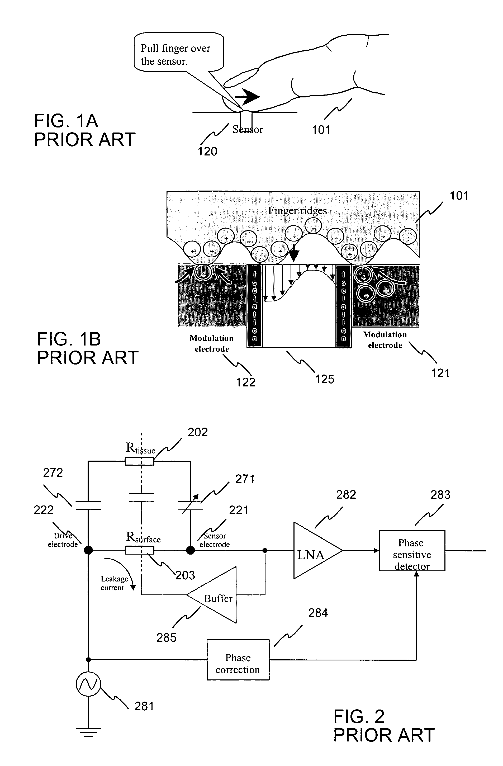
[0057]FIGS. 1A, 1B and 2 were explained above in the description of prior art.

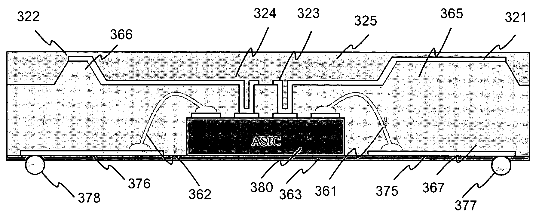
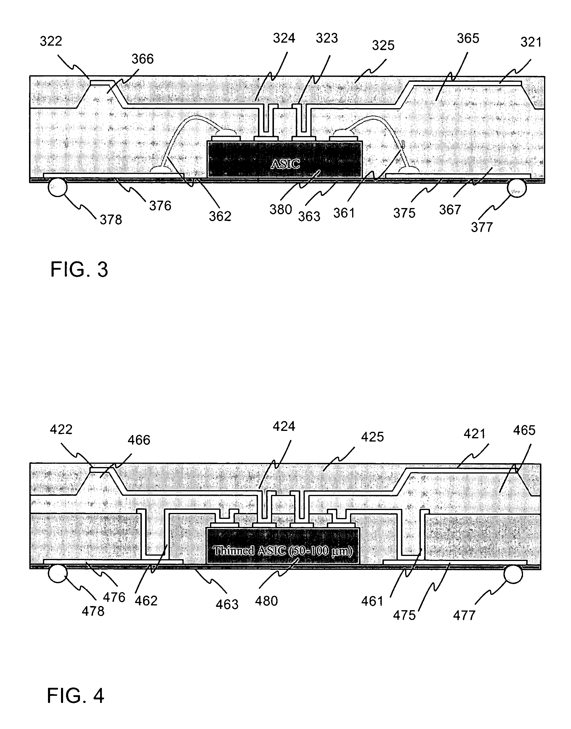
[0058]FIG. 3 illustrates a cross section of an exemplary arrangement according to the invention. The arrangement comprises a substrate 363, which is e.g. Kapton® film. The ASIC processing / measurement circuit 380 is attached on the carrier 363. The unit is connected to a printed circuit board by soldering from its soldering balls 377 and 378. The ASIC circuit is coupled electrically to the soldering balls by wire bonding 361, 362 to metallizations 375, 376 on the substrate. The driver electrode 321 and the sensing electrodes 322 are connected to the ASIC circuit with wires made by metallizations and vias, 323 and 324. The electrodes are made closer to the surface of the unit by producing polymer bumps 365 and 366 to the microreplicated polymer layer 367. The thickness of the bumps is e.g. 100-200 μm. On top of the unit there is encapsulation 325.

[0059]FIG. 4 illustrates a cross section of another exemplary ...


PUM

PropertyMeasurementUnit
areaaaaaaaaaaa
thicknessaaaaaaaaaa
heightaaaaaaaaaa

Abstract

A capacitive fingerprint sensor is fabricated on a plastic substrate (363) with an embedded integrated circuit chip (380). The invention describes a way to create two or three dimensional forms for electrode structures (321, 322, 325, 365, 366) that can be used to optimize the performance of the sensor. When the three dimensional structure is designed to follow the shape of a finger, a very small pressure is required when sliding the finger along the sensor surface. This way the use of the sensor is ergonomic and the measurement is made very reliable. The inventive fabrication method describes the way, how to connect and embed an integrated circuit containing measurement electronics with a batch processed larger scale electrode configuration that is used for capturing the capacitive image of the fingerprint.

Description

CROSS REFERENCE TO RELATED APPLICATION[0001]This application claims priority from Finnish application serial number 20030102 filed Jan. 22, 2003.TECHNICAL FIELD OF THE INVENTION[0002]The invention relates to an arrangement for authentication of a person, for example for authentication of a user of a mobile terminal. In particular the invention relates to a fingerprint sensor arrangement. The invention also relates to a manufacturing method of the inventive fingerprint sensor.BACKGROUND ART OF THE INVENTION[0003]There is a need of providing sensors in mobile terminals in order to make the mobile terminal capable of sensing its ambient conditions. The information can be used for context awareness applications where the ambient information is used for controlling the user interface profile and different settings of the mobile terminal user interface. Fingerprint sensors are also needed for authenticating the user of the terminal.[0004]There exist several kinds of fingerprint sensors: s...

Claims


Application Information

Patent Timeline
Patent Type & Authority Patents(United States)
IPC IPC(8): G06K9/00A61B5/117A61B5/1172
CPCG06K9/0002G06K9/00026Y10T29/49144Y10T29/49146H01L24/24H01L2224/8203H01L2224/92144H01L2224/48227H01L24/82H01L2924/15311H01L2224/73267H01L2224/04105H01L2224/24226G06V40/1335G06V40/1306H05K1/18G01D21/02
Inventor RYHANEN, TAPANIHJELT, KARI
Owner NOKIA TECH OY
Learn More