Object sensor and IC card reader with the object sensor

a technology of object sensor and ic card reader, which is applied in the field of object sensor, can solve the problems of inability to achieve high temperature characteristics, inability to say that the detection output sensitivity has reached a sufficient level, and the overall apparatus is prone to enlarge in size, so as to achieve accurate positioning, improve detection sensitivity, and improve the effect of electric current efficiency of the axial-end core portion

Inactive Publication Date: 2009-10-27
SANKYO SEIKI MFG CO LTD
View PDF5 Cites 45 Cited by
  • Summary
  • Abstract
  • Description
  • Claims
  • Application Information

AI Technical Summary

Benefits of technology

[0021]As described above, the axial-end core portion to be positioned close to the detection target object is formed to have the small width. Thereby, the electric current efficiency in the axial-end core portion is improved, and even more magnetic fluxes are generated, consequently enabling the detection sensitivity to be even more improved.
[0089]In the IC card reader according to the 31st embodiment of the invention, a magnetic differential inlet sensor is used as the inlet sensor described in the 30th embodiment of the invention thereby to enable a high-sensitive output to be obtained while using a small core body, notwithstanding environmental temperature variations. Accordingly, in addition to the above-described effects, a steady detection of the IC card can be implemented with high detection sensitivity. Consequently, a small and high-performance IC card reader can be obtained.

Problems solved by technology

Consequently, in the conventional object sensor, the detection output sensitivity cannot yet be said as having reached a sufficient level.
In addition, there is a problem in that high temperature characteristics cannot be obtained because of influences of factors such as temperature-caused variations in magnetic permeability of a DC resistor part.
Further, as is shown in FIG. 12, variations in three dimensional magnetic flux φr are utilized to increase the variation amount thereof, so that the overall apparatus is prone to be enlarged in size.
An additional problem is that since the impedance varies following the change in the length between a sensor amplifier and a cable, the amplifier should be tuned.
However, in the case that an IC card is used as a recent card, no specific proposal has been made regarding how to detect the validity of the IC card.
In the case that an eddy-current type sensor of the type disclosed in Japanese Unexamined Patent Application Publication No. 11-352108 is used to determine an IC card, there is a problem in that thinning of the card is disabled.
More specifically, in the case of the eddy-current type sensor, three or more excitation rod-shaped core bodies are disposed, so that enlargement of the apparatus cannot be averted.
Further, for recent IC-card using card readers of the type described above, a detailed proposal regarding how to detect card types has not been made to date.
As described above, the conventional card reader has problems in that it is incapable of determining the type of a card inserted in the apparatus mainbody; that is, it is incapable of determining whether a card being used at the present time is a magnetic card or an IC card.
In addition, in the case of an IC card, the card reader is incapable of determining whether the IC card is a contact IC card or contactless IC card, therefore completely disabling determining a common type of these cards, as a matter of course.
As such, when, for example, an unusable card is inserted, the control operation of closing the shutter cannot be securely performed whereby to disable countermeasures to prevent from being erroneous operations, damage, and / or the like of the apparatus.
However, in an event that, for example, wire disconnection has occurred inside the inlet sensor or between the inlet sensor and a signal processor circuit or the like, since the IC card cannot be appropriately sensed, there arises a problem in that even a correct IC card is erroneously recognized as being an incorrect card whereby rendering it unusable.
Nevertheless, in a general IC-card using card reader, wire disconnection and the like in the inlet sensor cannot be pre-detected.

Method used


Image

  • Object sensor and IC card reader with the object sensor
  • Object sensor and IC card reader with the object sensor
  • Object sensor and IC card reader with the object sensor

Examples


Embodiment Construction

[0139]First, embodiments of an object sensor according to the present invention will be described in detail with reference to the drawings.

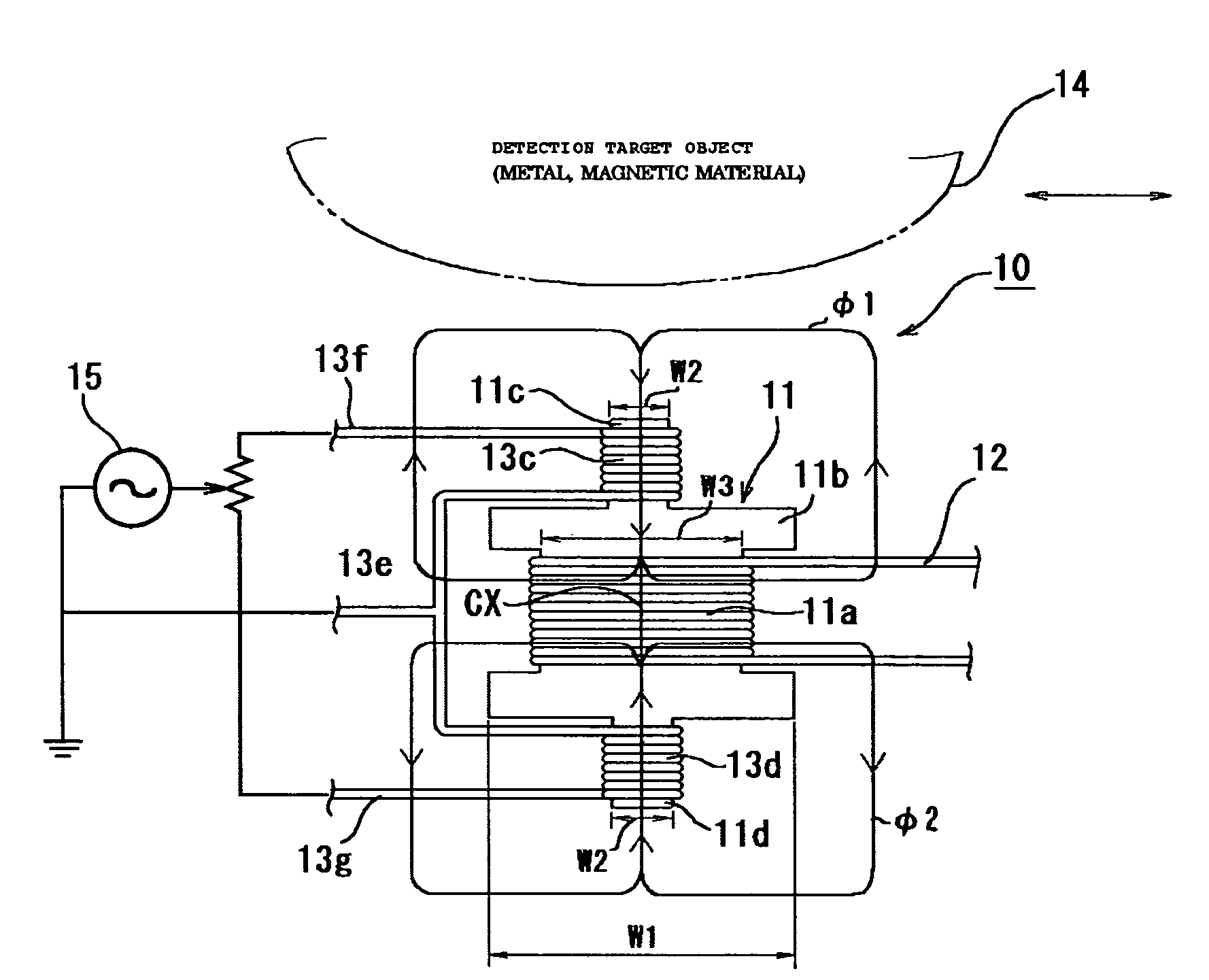
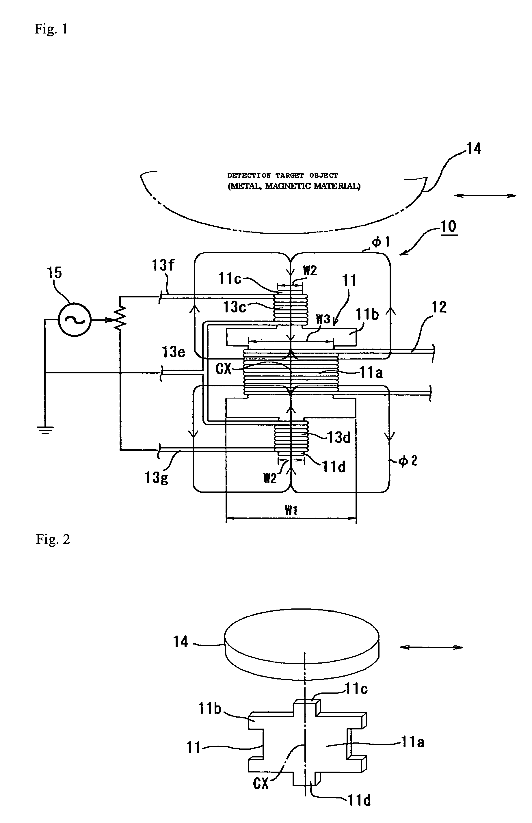
[0140]With reference to FIGS. 1 and 2, in an object sensor 10 according to one embodiment, a detecting coil 12 is wound around a central core portion 11a of a core body 11 formed of a single thin-plate shaped member. In addition, excitation coils 13c and 13d are respectively wound around individual axial-end core portions 11c and 11d in a pair integrally connected individually via engagement flange portions 11b on both sides of the central core portion 11a in the vertical direction as viewed in the drawing.

[0141]Of the axial-end core sections 11c and 11d in the pair, the axial-end core section 11c on the one side is disposed on the upper side as viewed in the drawing to face a detection target object 14 formed from a metal member or a magnetic material. In the present embodiment, the direction of an axial center CX (vertical direction as viewed i...


PUM


Abstract

The present invention provides an object sensor configured such that excitation coils (13c and 13d) and a detection coil (12) are separately disposed, and the detection is performed in accordance with the balance between the excitation coils (13c and 13d) in a pair, a residual variation amount after the impedance due to a DC resistance part and the like has been offset and removed is obtained at high sensitivity with excellent linearity while using a small core body (11), regardless of the impedance including a DC resistance part. Additionally, the object sensor to be used as an inlet sensor is located in an appropriate position on a more upstream side than the read / write position in an insertion direction of the IC card. A contact terminal portion of the IC card is sensed whereby to detect the validity of the card inserted into the apparatus from a card insertion slot. Thereby, steady detection operations can be implemented for the presence or absence of the IC card, notwithstanding environmental temperature variations.The invention further provides an IC card reader configured such that a plurality of inlet sensors for detecting the type of an inserted card is provided in appropriate positions more upstream than the read / write position in a card insertion direction, wherein when an unusable card or the like is inserted, a control operation of closing shutter means can be performed, thereby enabling illegal action with the card to be prevented.

Description

TECHNICAL FIELD[0001]The present invention relates to an object sensor formed to detect the presence or absence of a detection target object; and the invention further relates to an IC card reader that has the object sensor and that records and / or reproduce information on an IC card inserted to a read / write position in an apparatus mainbody.BACKGROUND OF THE INVENTION[0002]In general, object sensors are widely used with a wide variety of apparatuses including apparatuses for identifying irregular surfaces and materials of coins in coin-handling apparatuses, such as automatic vending machines, automatic ticket vending machines, ATMs, and motor rotation drive control apparatuses. Generally, conventional object sensors of the aforementioned type have an eddy-current type configuration as shown in FIG. 10 for example. Electric current is applied to a coil 200 wound on a rod-shaped core body 100 whereby to generate a detecting magnetic flux φr. In a magnetic field formed by the detecting...

Claims


Application Information

Patent Timeline
Patent Type & Authority Patents(United States)
IPC IPC(8): G06K7/08G06K7/00G06K13/08
CPCG06K13/08G06K7/0069
Inventor TAKITA, YUKIHIKOHIRASAWA, KENJIMOMOSE, SHOGOKITAZAWA, YASUHIRO
Owner SANKYO SEIKI MFG CO LTD
Why Eureka
Try Eureka