Flow-through mufflers with optional thermo-electric, sound cancellation, and tuning capabilities

a flow-through muffler and thermo-electric technology, applied in the field of mufflers, can solve the problems of back-pressure exerted on the engine, increase fuel consumption, and reduce engine performance, and achieve the effect of reducing engine fuel consumption

Inactive Publication Date: 2009-11-03
SULLIVAN JOHN TIMOTHY
View PDF88 Cites 32 Cited by
  • Summary
  • Abstract
  • Description
  • Claims
  • Application Information

AI Technical Summary

Benefits of technology

[0013]It is a first objective of the invention to provide a muffler that reduces engine fuel consumption.
[0014]It is a second objection of the invention to provide a muffler that reduces engine load while providing adequate sound attenuation, and that is simple to construct.
[0016]It is a fourth objective of the invention to provide a muffler having improved sound attenuation or cancellation characteristics, and that may easily be adapted for a particular acoustic profile.
[0018]It is a sixth objective of the invention to provide a muffler that is simple in construction and that may be easily adapted to meet any or all of the above objectives.
[0021]According to still further preferred embodiments of the invention, by providing a flow through muffler having at least two acoustic paths having different lengths between divergence and convergence, acoustic waves generated by the exhaust stream may be canceled. The difference between the lengths of the two paths may then be made variable, or paths of different lengths may be selectively closed off, according to a desired attenuation characteristic and / or in response to engine speed and load, resulting in a “tunable” muffler. Variation in the path lengths may be manual or automatic, in the former case permitting the user to increase or reduce the noise made by the vehicle according to preference, and in the latter case also permitting the muffler to operate at peak efficiency over a wide range of engine speeds and loads. Many racing vehicles, for example, have mufflers adapted to high speed operation that are ineffective at low speeds. The present invention solves this problem, enabling noise reduction both during and after a race.

Problems solved by technology

However, the material through which the gases are passed inherently cause back-pressure to be exerted on the engine.
Excess back-pressure increases fuel consumption and decreases engine performance.
No prior muffler has this capability.

Method used


Image

  • Flow-through mufflers with optional thermo-electric, sound cancellation, and tuning capabilities
  • Flow-through mufflers with optional thermo-electric, sound cancellation, and tuning capabilities
  • Flow-through mufflers with optional thermo-electric, sound cancellation, and tuning capabilities

Examples


Embodiment Construction

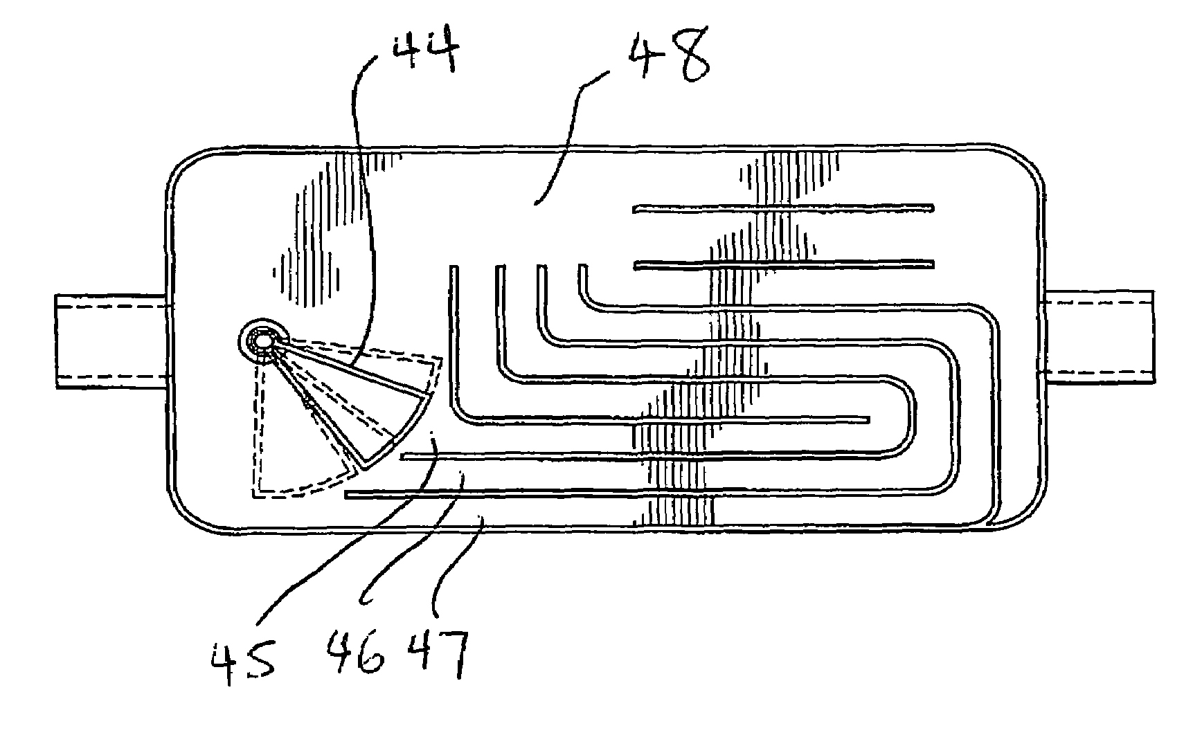
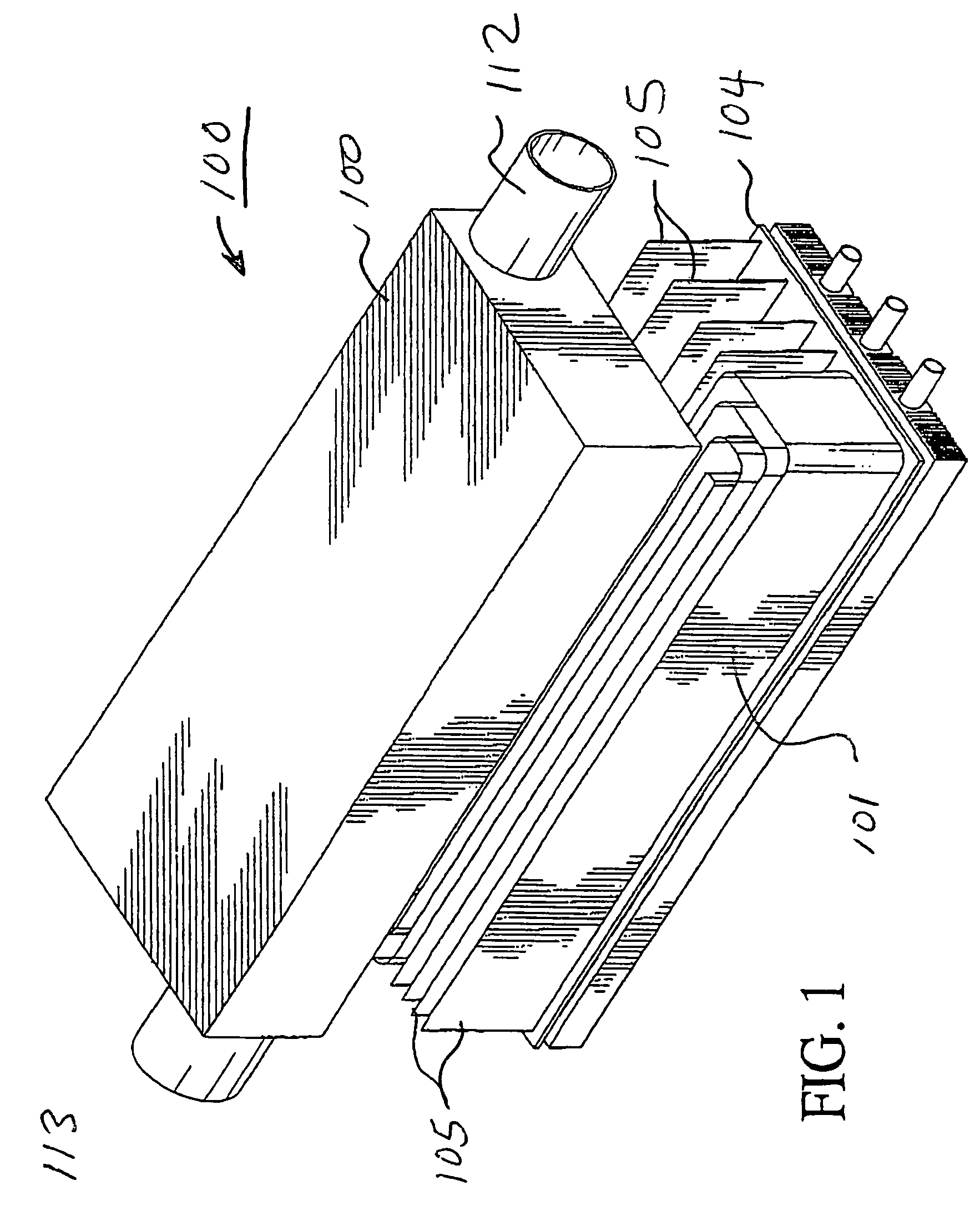
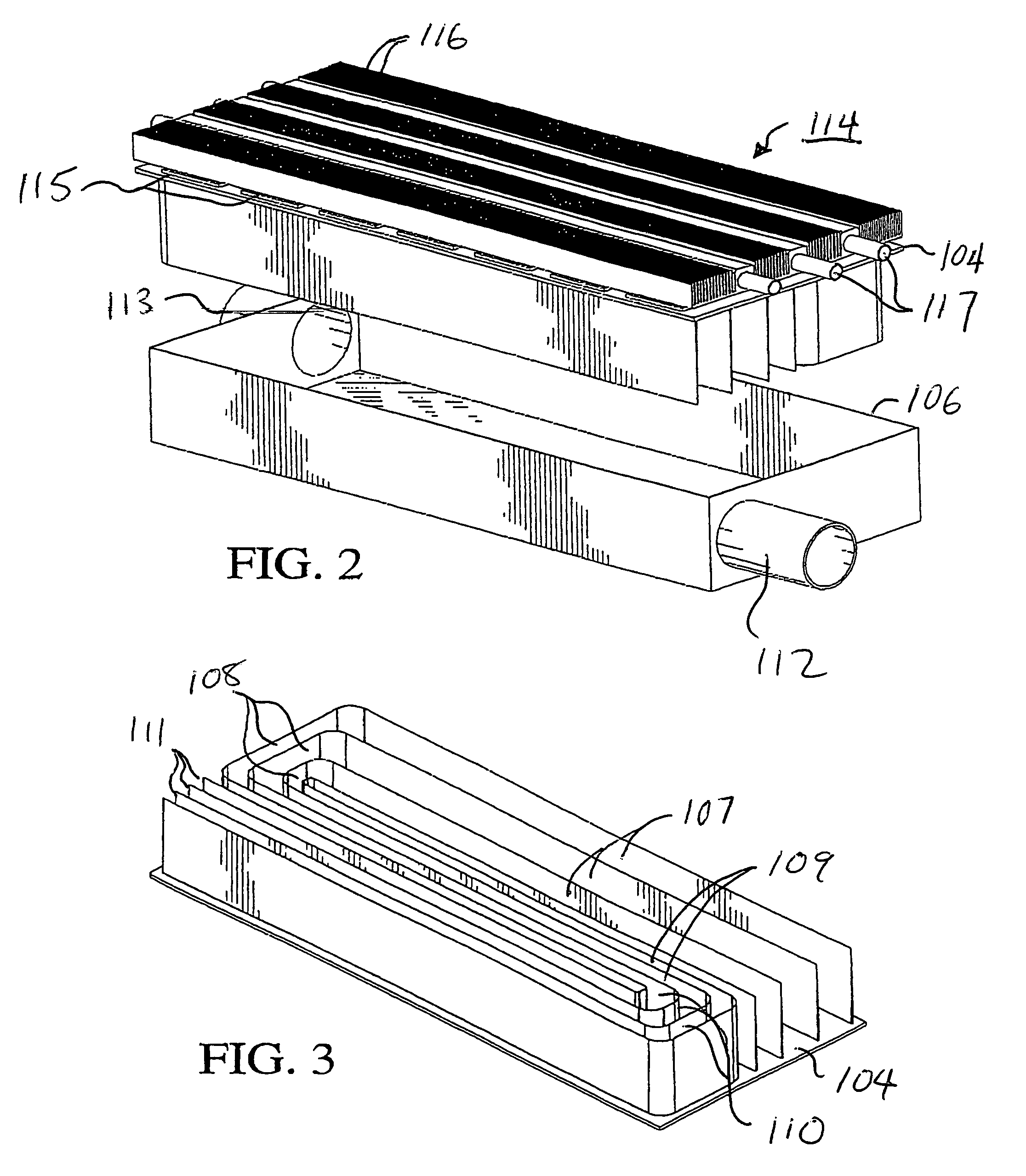
[0043]FIGS. 1-3 illustrate a flow-through muffler 100 constructed in accordance with the principles of a first preferred embodiment of the invention. Muffler 101 includes a first housing section 102 and a second housing section 103 which fit together to form an airtight container for passage of exhaust gases. Housing section 103 includes a cover 104 from which extend a plurality of walls 105. Cover 104 may be secured to the housing section 102 by welding, bolting, or any other suitable attachment means.

[0044]Partitions or baffles 105 are arranged to fit within housing section 102 when cover 104 is secured to the rim 106 of housing section 102 to thereby form a plurality of flow-through passages of gradually increasing width to decelerate exhaust gases, and having an s-shaped configuration consisting of straight exit sections 107, intermediate sections 108 extending transversely to straight sections 107, second straight sections 109 parallel to straight sections 107, second intermedi...


PUM


Abstract

A flow-through muffler includes a plurality of heat conducting walls, baffles, or partitions that together define a plurality of passages arranged to form acoustic waveguides, attenuators, and / or cancellation chambers, the walls, baffles, or partitions increasing a surface area exposed to the exhaust gases to facilitate extraction of heat while attenuating or canceling the resulting sound pressure waves. The muffler may have a cooling arrangement mounted thereon, and thermoelectric generator elements or other heat-powered device, such as a reformer, connected across the heat differential between the cooling arrangement and an exterior surface of the muffler housing that is in thermal contact with the heat conducting walls, bafflers, or partitions. In addition, the muffler may be made tuneable by providing a device for varying a length of one of the passages relative to another passage, and by including a sound cancellation chamber at an intersection of the passages. In addition, the internal surfaces of the muffler may be coated with a catalyst to provide a combination muffler and catalytic converter.

Description

BACKGROUND OF THE INVENTION[0001]1. Field of the Invention[0002]This invention relates to mufflers, and in particular to high efficiency mufflers arranged to reduce fuel consumption by decreasing back-pressure and therefore load on the engine. The mufflers feature flow-through passages and chambers defined by heat-conducting baffles or partitions that draw energy from the exhaust stream, the passages or chambers being acoustically configured to reduce exhaust noise: (a) by converting kinetic energy of the exhaust stream into heat energy; (b) by isolating and attenuating acoustic waves within the passages or chambers, and / or by partial or complete cancellation of the acoustic waves.[0003]The use of heat conducting baffles or passages enables the mufflers of the preferred embodiments to be used not only for sound reduction, but also for electricity generation. This is accomplished by using the heat carried away by the baffles or partitions to power thermoelectric generators to further...

Claims


Application Information

Patent Timeline
Patent Type & Authority Patents(United States)
IPC IPC(8): F01N1/08
CPCF01N1/02F01N1/083F01N1/084F01N1/163F01N1/165F01N1/166F01N13/1888F01N5/025H01L35/30F01N5/02F01N2230/00F01N2490/16Y02T10/16Y02T10/12H10N10/13
Inventor SULLIVAN, JOHN TIMOTHY
Owner SULLIVAN JOHN TIMOTHY
Why Eureka
Try Eureka