Window membrane for detector and analyser devices, and a method for manufacturing a window membrane

a detector and analyser technology, applied in the field of reinforced membranes, can solve the problems of disturbingly large collimating effect of reinforcement grid, unfavorable mechanical characteristics, and inability to adjust to temperature changes, etc., and achieves low unit cost, good yield, and advantageous mechanical characteristics.

Inactive Publication Date: 2009-11-17
OXFORD INSTUMENTS ANALYTICAL LIMITED
View PDF9 Cites 28 Cited by
  • Summary
  • Abstract
  • Description
  • Claims
  • Application Information

AI Technical Summary

Benefits of technology

[0012]An objective of the present invention is to present a window membrane and a window member that has advantageous mechanical characteristics and isotropic permeability. Another objective of the invention is to present a window membrane and a window member that is widely applicable to different kinds of detector and analyzer devices. A yet another objective of the invention is to present a method for manufacturing the window membrane and the window member mentioned above in a way that has low unit cost and good yield.
[0017]Materials such as tungsten that have good tensile strength do not need to be thick to make a mesh that can withstand considerable pressure in the direction perpendicular to the mesh. This property has been previously utilized in solutions where a complete window consists of a stack of a reinforced window membrane and a separate support mesh. The present invention introduces a composite structure, in which a reinforcement mesh is permanently attached to one surface of the window film. An advantageous material for attaching is a positive-working photosensitive glue, where “positive-working” means that unexposed parts solidify whereas exposed parts can be easily removed later in the process. Using a positive-working photosensitive glue is especially advantageous, because the reinforcement mesh can itself act also as an exposure mask.

Problems solved by technology

However, the reinforcement grid is not made of the substrate material of the manufacturing time, but of a photosensitive polymer that is spread on top of the window film.
There are certain drawbacks in the membrane structures that follow the principle of FIG. 1.
Using silicon as the combined substrate and reinforcement material results in modest tolerance of changes in temperature.
If the gap width C becomes smaller than the reinforcement thickness D, the collimating effect of the reinforcement grid begins to grow disturbingly large.
This is often an undesired characteristic.
Making the gap width larger would diminish the collimating effect, but this requires also increasing the thickness of the window film, which in turn increases unwanted attenuation.
Additionally a larger structural module of the reinforcement mesh makes the thermal expansion problems worse.
However, such an arrangement has the inherent drawback that the support mesh only helps against a pressure difference in one direction.
Using two support meshes, one on each side, would introduce too much attenuation, especially if the meshes were not perfectly aligned, which is difficult.

Method used


Image

  • Window membrane for detector and analyser devices, and a method for manufacturing a window membrane
  • Window membrane for detector and analyser devices, and a method for manufacturing a window membrane
  • Window membrane for detector and analyser devices, and a method for manufacturing a window membrane

Examples


Embodiment Construction

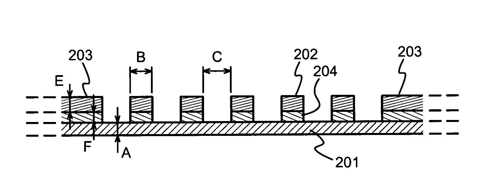
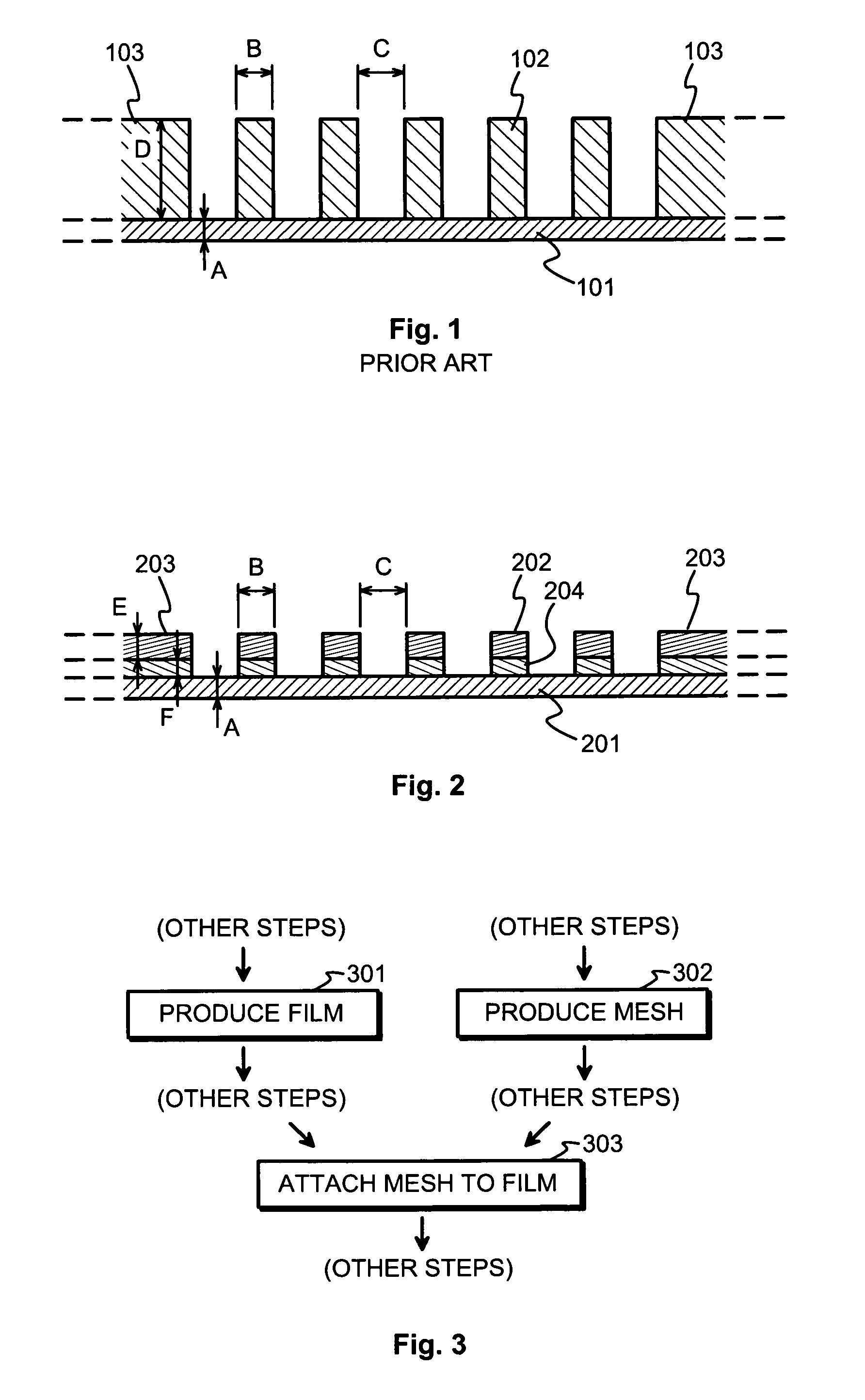
[0025]FIG. 2 illustrates schematically a composite membrane structure according to a principal embodiment of the invention. The basic structural parts of the membrane are a continuous window film 201 and a reinforcement mesh 202. Since FIG. 2 is a cross-section drawing, only some portions of the reinforcement mesh are visible in the form of hatched rectangles. The reinforcement mesh may continue as extended solid portions 203 towards the edges of the window to facilitate more reliable fitting to a frame (not shown in FIG. 2). Between the reinforcement mesh 202 and the window film 201 there is a layer of solid material 204, which acts like a glue and attaches the reinforcement mesh 202 to the surface of the window film 201.

[0026]FIG. 3 illustrates an excerpt of a manufacturing process, in which at some previous manufacturing steps 301 and 302 there are formed a window film and a reinforcement mesh respectively. At some later step 303 in the process, the window film and the reinforcem...


PUM

PropertyMeasurementUnit
thicknessaaaaaaaaaa
thicknessaaaaaaaaaa
thicknessaaaaaaaaaa

Abstract

A window membrane is permeable to electromagnetic radiation, especially soft X-rays. It comprises a film (201) and a metallic reinforcement mesh (202) attached to the film (201). A preferable way of attaching the metallic reinforcement mesh (202) to the film is to use a positive-working photosensitive glue (204) and allow the reinforcement mesh (202) to act as the exposure mask.

Description

TECHNICAL FIELD[0001]The invention concerns generally the technology of reinforced membranes that have certain desired transmission characteristics of electromagnetic radiation. Especially the invention concerns a membrane that can be used as a window in X-ray detector and analyzer devices.BACKGROUND OF THE INVENTION[0002]The inside of an X-ray detector and / or analyzer appliance, or at least the inside of the component in which X-rays propagate, is often evacuated to a degree at which for practical purposes it constitutes a vacuum. A window in the wall of the vacuum container, through which the X-rays should pass, must fulfill contradictory requirements. On one hand it should attenuate the soft X-rays as little as possible, in order not to interfere with the measurement. On the other hand it must be mechanically strong enough to withstand the pressure difference.[0003]In this description we use the term “film” to mean a thin material layer of uniform thickness, and the term “membran...

Claims


Application Information

Patent Timeline
Patent Type & Authority Patents(United States)
IPC IPC(8): D03D9/00B05D7/14H01J33/04H01J35/18H01J5/18B32B27/06B32B27/12B32B3/30D03D19/00H01J35/00H01J5/02
CPCH01J47/004H01J5/18Y10T442/10Y10T442/109Y10T442/126Y10T442/131Y10T442/164Y10T442/169Y10T442/339Y10T442/3447
Inventor MEILAHTI, TOMI
Owner OXFORD INSTUMENTS ANALYTICAL LIMITED
Why Eureka
Try Eureka