Composite electrolyte membrane, catalyst-coated membrane assembly, membrane-electrode assembly and polymer electrolyte fuel cell

a technology of polymer electrolyte and membrane, applied in the field of polymer electrolyte fuel cells, can solve the problems of polymer electrolyte membrane , difficulty in alignment, and achieve excellent mechanical strength, prevent the effect of size change, and excellent size stability

Inactive Publication Date: 2009-11-24
PANASONIC CORP
View PDF9 Cites 4 Cited by
  • Summary
  • Abstract
  • Description
  • Claims
  • Application Information

AI Technical Summary

Benefits of technology

[0030]Because the composite electrolyte membrane of the present invention has the structure described above, and the reinforcement layer and the electrolyte layer are laminated such that the X1 axis direction having a high tensile modulus of elasticity in the reinforcement layer substantially corresponds with the X2 axis direction having a high rate of size change in the electrolyte layer, the size change of the electrolyte layer in the direction of the X2 axis is effectively prevented by the high tensile modulus of elasticity of the reinforcement layer in the direction of the X1 axis.
[0049]Further, according to the present invention, by using the aforesaid composite electrolyte membrane, it is possible to easily and surely obtain a catalyst-coated membrane assembly, a membrane-electrode assembly and a polymer electrolyte fuel cell which are highly reliable and capable of exhibiting sufficient cell performance for a long period of time.

Problems solved by technology

Accordingly, problems arise during the production of a cell or stack in the manufacturing process of a polymer electrolyte fuel cell such as difficulty in alignment of the polymer electrolyte membrane 111 and formation of wrinkles in the polymer electrolyte membrane 111.
Further, the polymer electrolyte membrane 111 usually has insufficient mechanical strength, and therefore it might be damaged during the production or operation of a polymer electrolyte fuel cell.
However, even with the use of the techniques proposed by Patent Documents 1 to 3, the size change of a water impregnated polymer electrolyte membrane could not be suppressed sufficiently.
In addition thereto, the mechanical strength of the polymer electrolyte membrane was not sufficient, either.
In other words, even when the techniques disclosed in Patent Documents 1 to 3 are used, the size of a polymer electrolyte membrane varies depending on the water impregnated condition, the polymer electrolyte membrane is displaced during the production of a cell or stack, wrinkles are caused in the polymer electrolyte membrane, or the polymer electrolyte membrane is damaged during the production or operation of a polymer electrolyte membrane.

Method used


Image

  • Composite electrolyte membrane, catalyst-coated membrane assembly, membrane-electrode assembly and polymer electrolyte fuel cell
  • Composite electrolyte membrane, catalyst-coated membrane assembly, membrane-electrode assembly and polymer electrolyte fuel cell
  • Composite electrolyte membrane, catalyst-coated membrane assembly, membrane-electrode assembly and polymer electrolyte fuel cell

Examples


embodiment 1

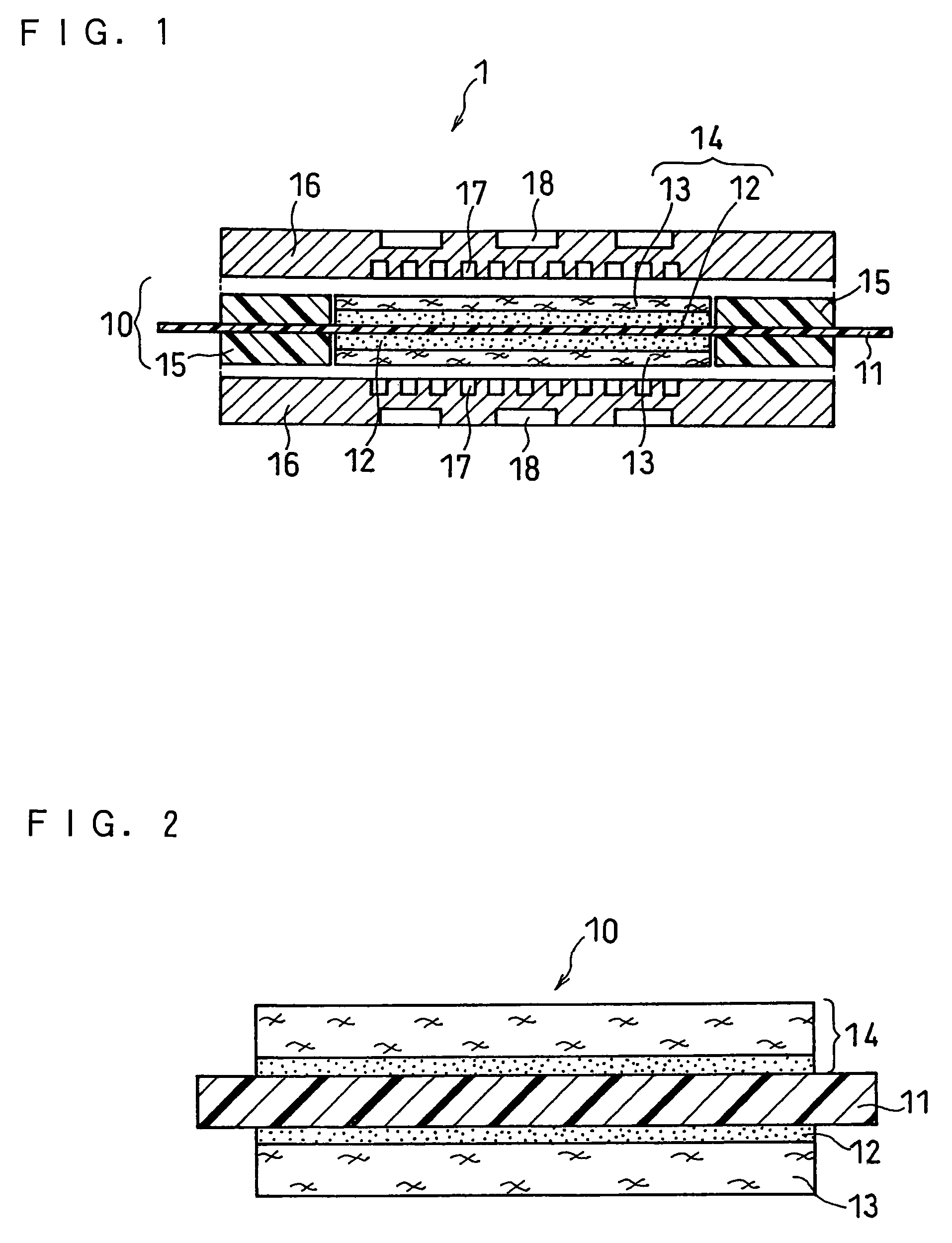
[0069]FIG. 1 is a schematic cross sectional view illustrating a basic structure of a unit cell designed to be mounted in a polymer electrolyte fuel cell according to Embodiment 1 of the present invention. FIG. 2 is a schematic cross sectional view illustrating a basic structure of a membrane-electrode assembly (MEA) designed to be mounted in the unit cell 1 shown in FIG. 1.

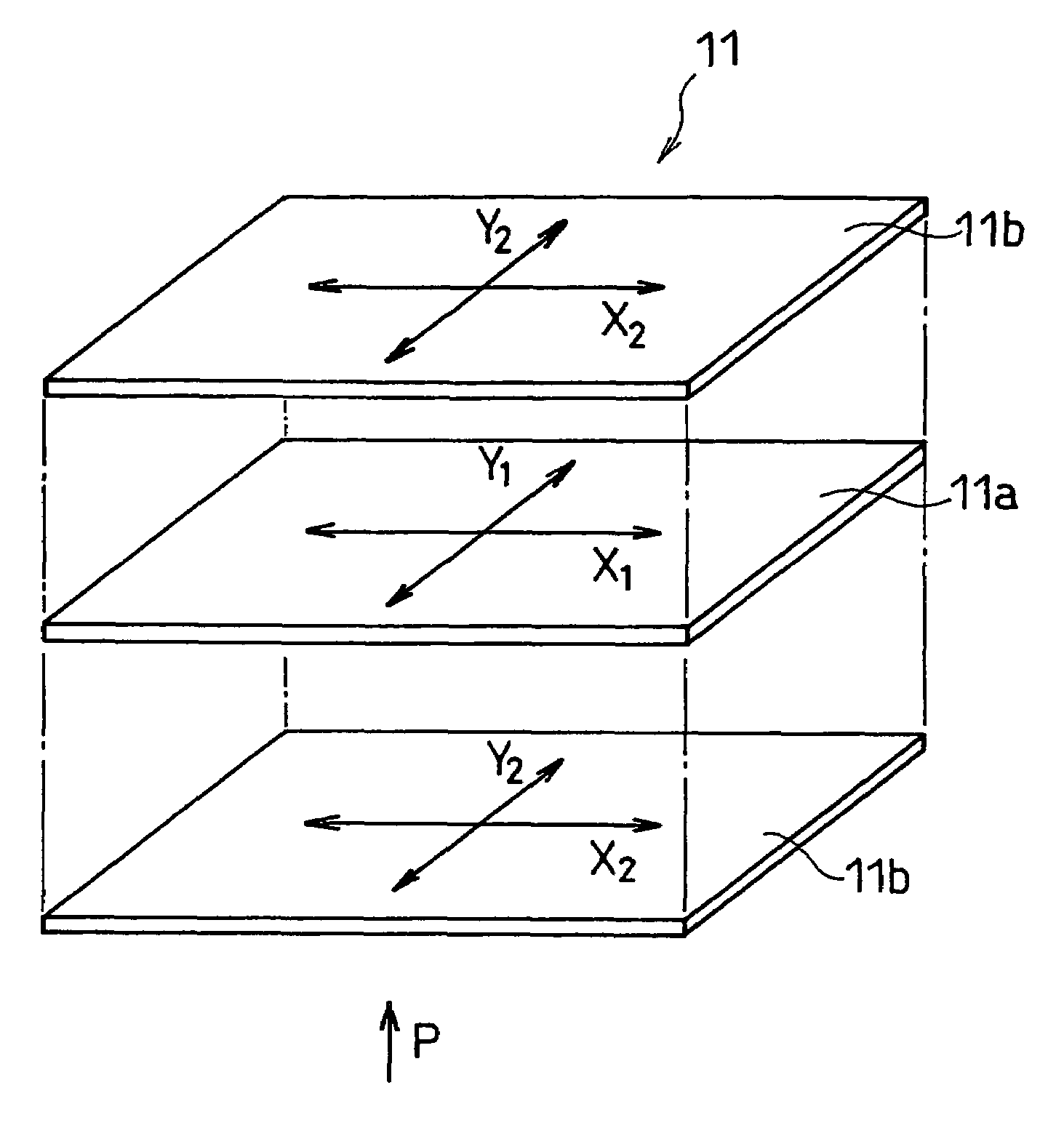
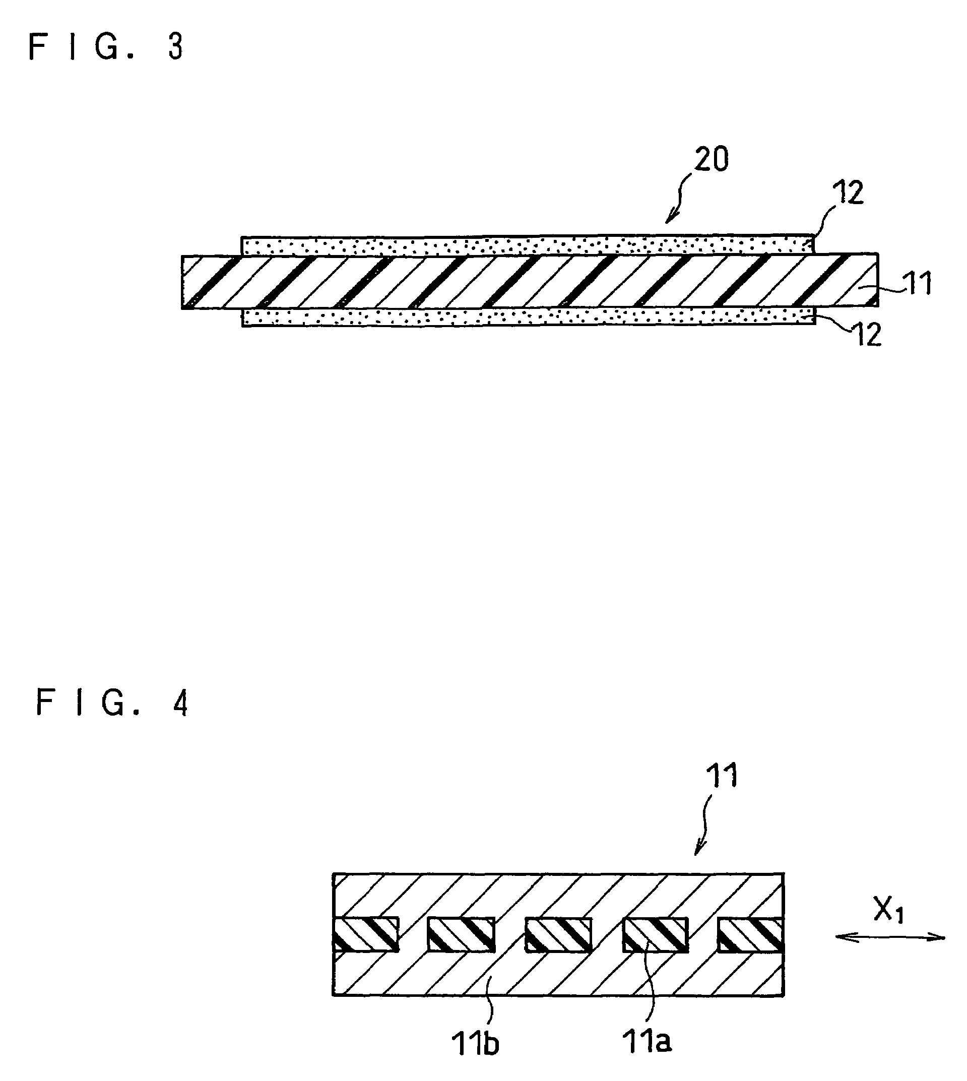
[0070]FIG. 3 is a schematic cross sectional view illustrating a basic structure of a catalyst-coated membrane assembly designed to be mounted in the membrane-electrode assembly 10 shown in FIG. 2. FIG. 4 is a schematic cross sectional view illustrating a composite electrolyte membrane 11 to be mounted in the catalyst-coated membrane assembly 20 shown in FIG. 3.

[0071]As shown in FIGS. 1 to 3, in a membrane-electrode assembly 10 and a catalyst-coated membrane assembly 20, on each surface of a composite electrolyte membrane 11 of the present invention including an electrolyte layer made of a polymer electrolyte capab...

embodiment 2

[0162]A description will now be given of a polymer electrolyte fuel cell according to Embodiment 2 of the present invention. A polymer electrolyte fuel cell according to Embodiment 2 (not shown in the drawings) has a structure identical to that of the polymer electrolyte fuel cell 1 according to Embodiment 1 shown in FIG. 1 except that the structure of the composite electrolyte membrane 11 is changed.

[0163]In the following, a composite electrolyte membrane 41 (a composite electrolyte membrane according to Embodiment 2 of the present invention) included in a polymer electrolyte fuel cell 1 according to Embodiment 2 will be described.

[0164]FIG. 12 is an enlarged cross sectional view of a relevant part of a composite electrolyte membrane 41 included in a polymer electrolyte fuel cell according to Embodiment 2 of the present invention.

[0165]In the composite electrolyte membrane 41 in a polymer electrolyte fuel cell according to Embodiment 2, an electrolyte layer 41b is formed on one sur...

embodiment 3

[0170]A description will now be given of a polymer electrolyte fuel cell according to Embodiment 3 of the present invention. A polymer electrolyte fuel cell according to Embodiment 3 (not shown in the drawings) has a structure identical to that of the polymer electrolyte fuel cell 1 according to Embodiment 1 shown in FIG. 1 except that the structure of the composite electrolyte membrane 11 is changed.

[0171]In the following, a composite electrolyte membrane 51 (a composite electrolyte membrane according to Embodiment 3 of the present invention) included in a polymer electrolyte fuel cell 1 according to Embodiment 3 will be described.

[0172]FIG. 13 is an enlarged cross sectional view of a relevant part of a composite electrolyte membrane 51 included in a polymer electrolyte fuel cell according to Embodiment 3.

[0173]The composite electrolyte membrane 51 in a polymer electrolyte fuel cell according to Embodiment 3 is composed of two composite electrolyte membranes 41 according to Embodim...


PUM

PropertyMeasurementUnit
porosityaaaaaaaaaa
electromotive forceaaaaaaaaaa
lengthaaaaaaaaaa

Abstract

To provide a polymer electrolyte membrane having excellent size stability and excellent mechanical strength that can sufficiently prevent the size change due to the swelling condition, the displacement of the polymer electrolyte membrane and the formation of wrinkles during the production of the polymer electrolyte fuel cell, and can prevent damage during the production and operation of the polymer electrolyte fuel cell. In a composite electrolyte membrane including a porous reinforcement layer made of a resin and an electrolyte layer made of a polymer electrolyte and laminated at least one main surface of the reinforcement layer, the direction having a high tensile modulus of elasticity in the reinforcement layer is substantially corresponded with the direction having a high rate of size change in the electrolyte layer.

Description

BACKGROUND OF THE INVENTION[0001]The present invention relates to a polymer electrolyte fuel cell using hydrogen, methanol, methanol or dimethyl ether as a fuel and air or oxygen as an oxidant. More specifically, the present invention particularly relates to a composite electrolyte membrane, a catalyst-coated membrane assembly and a membrane-electrode assembly.[0002]Conventional polymer electrolyte fuel cells employing a cation (hydrogen ion) conductive polymer electrolyte generate electricity and heat by electrochemically reacting a fuel gas containing hydrogen and an oxidant gas containing oxygen such as air.[0003]FIG. 17 is a schematic cross sectional view illustrating a basic structure of a unit cell designed to be mounted in a conventional polymer electrolyte fuel cell. FIG. 18 is a schematic cross sectional view illustrating a basic structure of a membrane-electrode assembly designed to be mounted in the unit cell 110 shown in FIG. 17. As shown in FIG. 17, in a membrane-electr...

Claims


Application Information

Patent Timeline
Patent Type & Authority Patents(United States)
IPC IPC(8): H01M4/00H01M6/04H01M8/10H01M8/02H01M4/86H01M4/88H01M4/92H01M8/24
CPCH01M4/881H01M4/8828H01M8/026H01M8/1002H01M8/1053H01M8/106H01M8/1062H01M8/241H01M8/0291H01M4/8605H01M4/886H01M4/921Y02E60/521H01M8/1004H01M8/0263H01M8/0289H01M8/242H01M8/1007H01M8/2483Y02E60/50Y02P70/50H01M8/02H01M8/10
Inventor HORI, YOSHIHIROYOSHIDA, AKIHIKOYOSHIMURA, MIKIKOUCHIDA, MAKOTOKINOSHITA, SHINJIWAKABAYASHI, HIROKAZU
Owner PANASONIC CORP
Why Eureka
Try Eureka