Pneumatic dry wall sander

a dry wall sander and pneumatic technology, applied in the field of construction, can solve the problems of affecting the useful life of electrical tools, dust and other items, affecting the entire parts of drywall sanding equipment, etc., and achieve the effect of reducing the possibility of health problems and being safer for users

Inactive Publication Date: 2009-12-01
GORDON JEFF
View PDF13 Cites 14 Cited by
  • Summary
  • Abstract
  • Description
  • Claims
  • Application Information

AI Technical Summary

Benefits of technology

[0011]Additionally the inhalation of drywall dust may be associated with health problems and the vacuum system in this device would greatly reduce the possibility of health problems for the workers.
[0012]It is an object of this device to have a pneumatically operated dry wall sander, which would remove the necessity of having a source of electrical current while at the same time vacuuming the dust that is produced in the sanding process and distributing the dust to a remote location.
[0013]It is a further object to make a device, which is safer for the user in terms of general productivity as well as health issues.

Problems solved by technology

This use of pneumatics saves a great deal of money and time during the sanding operation and saves time and money during the initial set up at the site.
During the sanding process, it is very common to have dust and other items impact all parts of the drywall sanding equipment including the operator of the equipment.
Unfortunately, the effect of an excessive amount of dust on electrical equipment is to shorten the useful life of the electrical tool, including a drywall sander.
Dust will collect on the armature of the electrical motor, the brushes of the electrical motor and short its life expectancy.
Additionally, the dust will also impact the user of the device and result in greatly reduced productivity as well as general skin irritation and other possible health hazards.
As the dust is literally flying the dust will cake on the user and the user will be forced to take multiple breaks to clean his or her eyes.
Safety goggles are not useful to combat this problem because the dust simply accumulates on the goggles.
This results in frequent breaks and a great deal of down time with a resultant loss of productivity.

Method used


Image

  • Pneumatic dry wall sander
  • Pneumatic dry wall sander
  • Pneumatic dry wall sander

Examples


Embodiment Construction

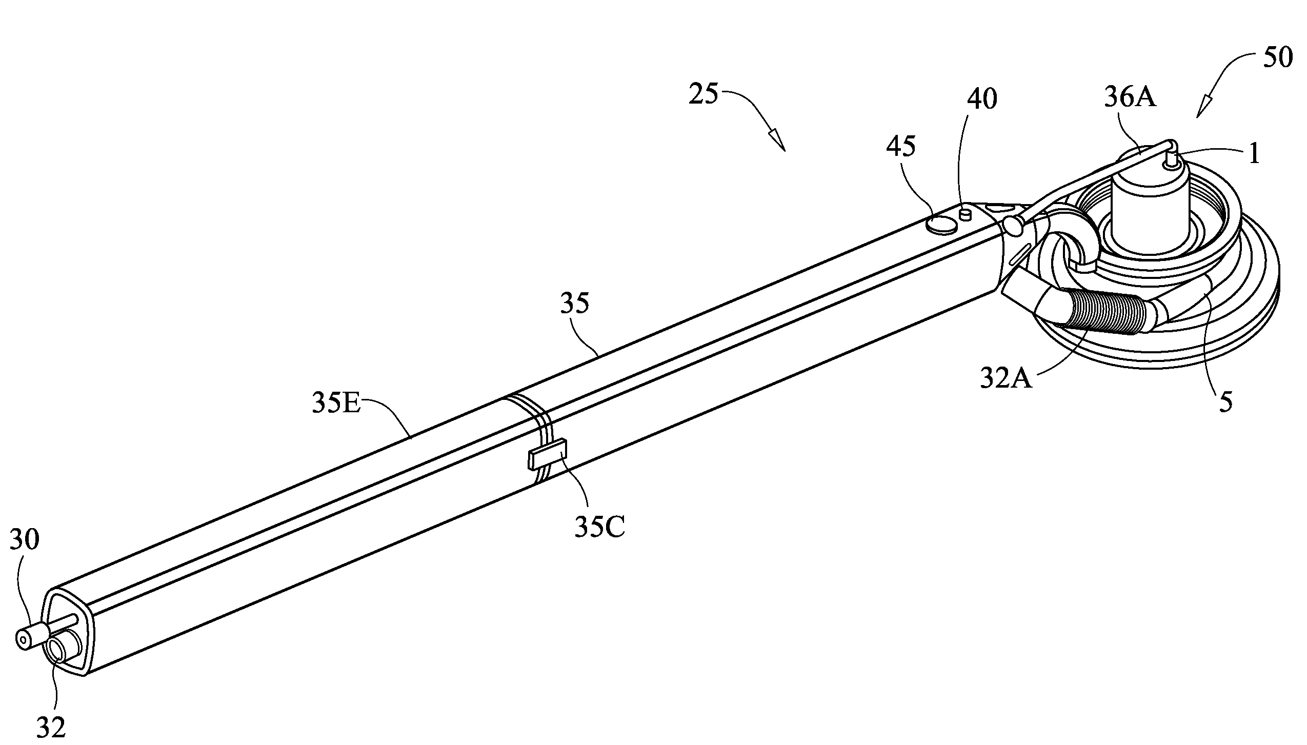
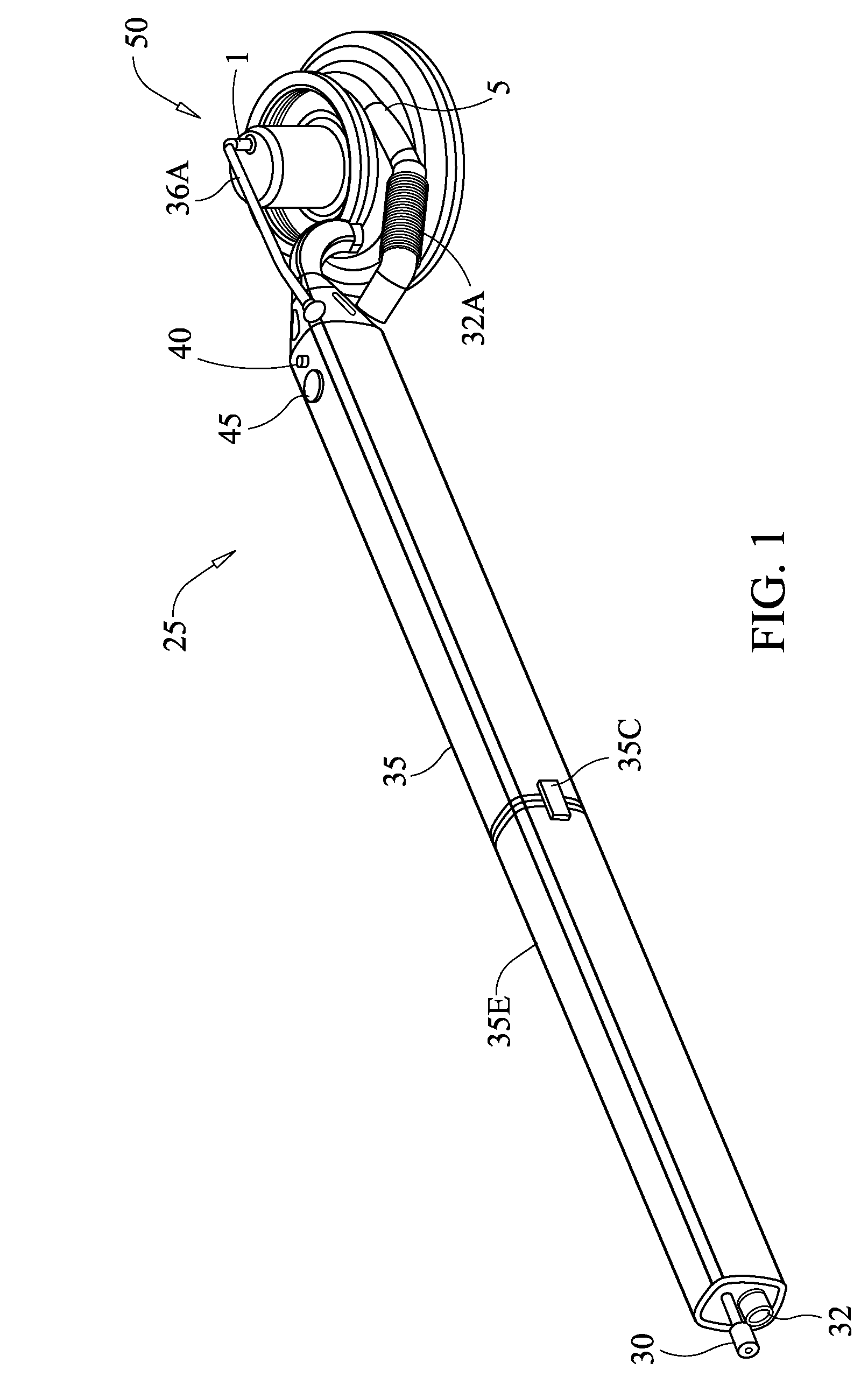
[0018]This device 25 is a pneumatically operated sander with the added feature of vacuuming the dust that is generated during the sanding process. Pneumatic tools, in general, are common in the prior art as well as pneumatic sanders. However, in addition to performing the sanding functions the device will also create a slight vacuum that will capture the dust and discard it without interfering with the operation of the sander.

[0019]The sander assembly 50 is attached to a handle 35 that allows the person to maneuver the sander while on the wall to be sanded. Within the handle 35 will be flexible tubing to supply 30 air to the sander and flexible tubing to exhaust 32 the dust. Both the air supply and the exhaust port will be attached to respective portions of the casing.

[0020]Extension members 35E may be connected to the handle 35 and used with this device to extend the length of the device. A means to connect the sections 35C is also provided. Air supply tubing 30 will be placed in t...


PUM


Abstract

This invention is a pneumatically driven dry wall sander with the capability to create a vacuum to trap the dust, which is produced during the sanding operation, and then safely eject the dust away from the work site. A pneumatic motor that is operated by air will operate the sander and sanding disk and at the same time operate a set of impellers that create a slight vacuum. The air flow can be regulated so that the speed of the motor can be controlled depending on the specific need of the worker in performing sanding operations.

Description

BACKGROUND OF THE INVENTION[0001]A. Field of the Invention[0002]This device will be used in the construction trades and specifically when sanding a wall. Sanding the walls is necessary in the construction of new homes particularly prior to the application of paint on the interior walls and ceiling. In the past, electrical sanders have been used. Because of the amount of dust that is inevitably and unavoidably produced during the sanding process, electrical equipment wears out quickly because of the exposure to high levels of contaminants that enter into the electrical equipment.[0003]B. Prior Art[0004]There are many other references in the prior art related to dry wall sanders. A representative example is Conboy, U.S. Pat. No. 6,468,141. Another example is Loveless, U.S. Pat. No. 6,860,799. The Conboy device is a dry wall sander, which is operated using an electrical motor. The Loveless device is a vacuum-driven sander.[0005]Neither of the above referenced devices operate using a pn...

Claims


Application Information

Patent Timeline
Patent Type & Authority Patents(United States)
IPC IPC(8): B24B23/03B24B55/06
CPCB24B7/184B24B55/10B24B23/026
Inventor GORDON, JEFF
Owner GORDON JEFF
Why Eureka
Try Eureka