Catheter kit for burrow

a catheter kit and kit technology, applied in the field of catheter kits, can solve the problems of difficult to completely fix, evulsion inability to maintain the embedding state of catheter in stomach, etc., and achieve the effect of shortening the working time, enhancing the operability of the operator, and alleviating the burden on the patien

Inactive Publication Date: 2009-12-01
YUTAKA SUZUKI +1
View PDF31 Cites 57 Cited by
  • Summary
  • Abstract
  • Description
  • Claims
  • Application Information

AI Technical Summary

Benefits of technology

[0018]In addition, the present invention provides the aforementioned catheter kit for a fistula, wherein a tip part of the tube is further provided with a one-way valve for preventing a counterflow from an interior of stomach to outside of a body via a nutrient passage.
[0034]In addition, according to the present invention, the same effect as that of the aforementioned invention is exerted, additionally, while the state where an internal indwelling part of a catheter is pushed and expanded is locked, a catheter can be inserted into stomach, and operation becomes further easy.

Problems solved by technology

However, when the internal indwelling part is a balloon-type, it is unexpectedly deformed due to damage such as rupture thereof, the embedded state of a catheter in stomach can not be maintained, and there is a possibility that the catheter is evulsed from stomach.
Upon this insertion, a stomach wall is fixed with a suture thread so that the stomach wall is not freely moved relative to an abdominal wall, but actually, it is difficult to completely fix it, and when a stomach fistula is not properly provided, acute peritonitis is caused in some cases.
However, in this case, since a direction that the preparing part 201 of the hollow rod 200 is pushed with a finger is outside of a central axis of the hollow rod 200, there is a problem that a force is not effectively transmitted from the hollow rod 200 to the internal indwelling part 102 of the catheter 100.
In this case, since an external force is not concentrated on the internal indwelling part, operation for further enhancing an external force is performed in some cases, and operation of inserting into a body becomes more difficult.
In addition, in the previous catheter kit for a fistula, there is a problem that, when one tries to push and expand an internal indwelling part with an obturator or a hollow rod, at an abutment part, an obturator or a hollow rod breaks a tip of an internal indwelling part, projecting therefrom, and the internal indwelling part can not be inserted in a body.
Further, the previous catheter kit for a fistula has a problem that operation of pushing and expanding an internal indwelling part 102 of the catheter 100, and operation of inserting the catheter 100 in stomach must be done at the same time, and an operating ability and operation technique are required as compared with a method of successively performing individual operations.

Method used


Image

  • Catheter kit for burrow
  • Catheter kit for burrow
  • Catheter kit for burrow

Examples


first embodiment

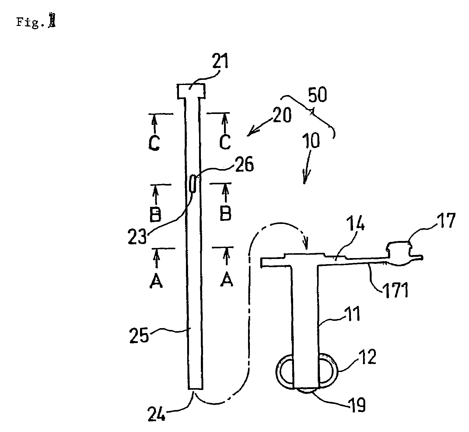
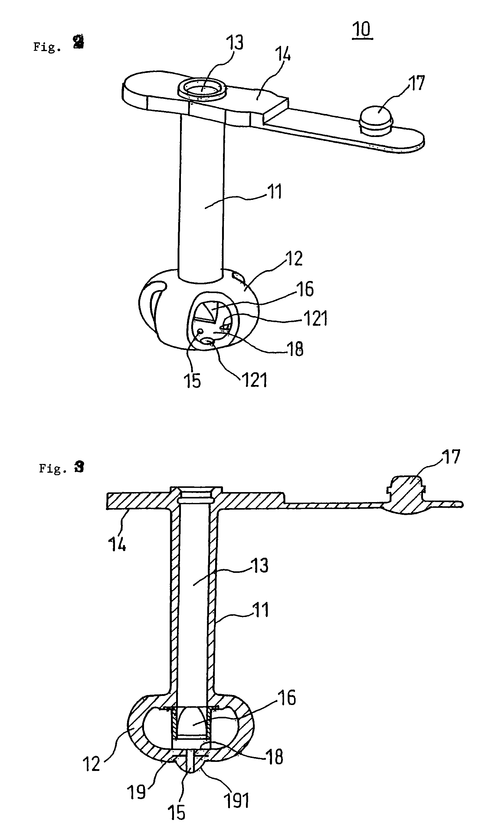
[0057]Then, the catheter kit for a fistula in the present invention will be explained by referring to FIG. 1 to FIG. 7. FIG. 1 is a schematic view of a catheter and an obturator constituting the catheter kit for a fistula in the free state of this example, FIG. 2 is a perspective of the catheter of FIG. 1, FIG. 3 is a longitudinal cross-sectional view of the catheter of FIG. 1, FIG. 4 (A) is an enlarged end view seen along an A-A line of FIG. 1, (B) is an enlarged end view seen along a B-B line of FIG. 1, (C) is an enlarged end view seen along a C-C line of FIG. 1, FIG. 5 is a schematic view of the catheter kit for a fistula in the external force acting state of this example, FIG. 6 is an enlarged view of a tip part of the catheter of FIG. 1, and FIG. 7 is an illustration view showing one example of a one-way valve. Herein, the “tip” refers to a side in a body, and the “rear end” refers to an extracorporeal side.

[0058]The catheter kit for a fistula 50 in the first embodiment is cons...

second embodiment

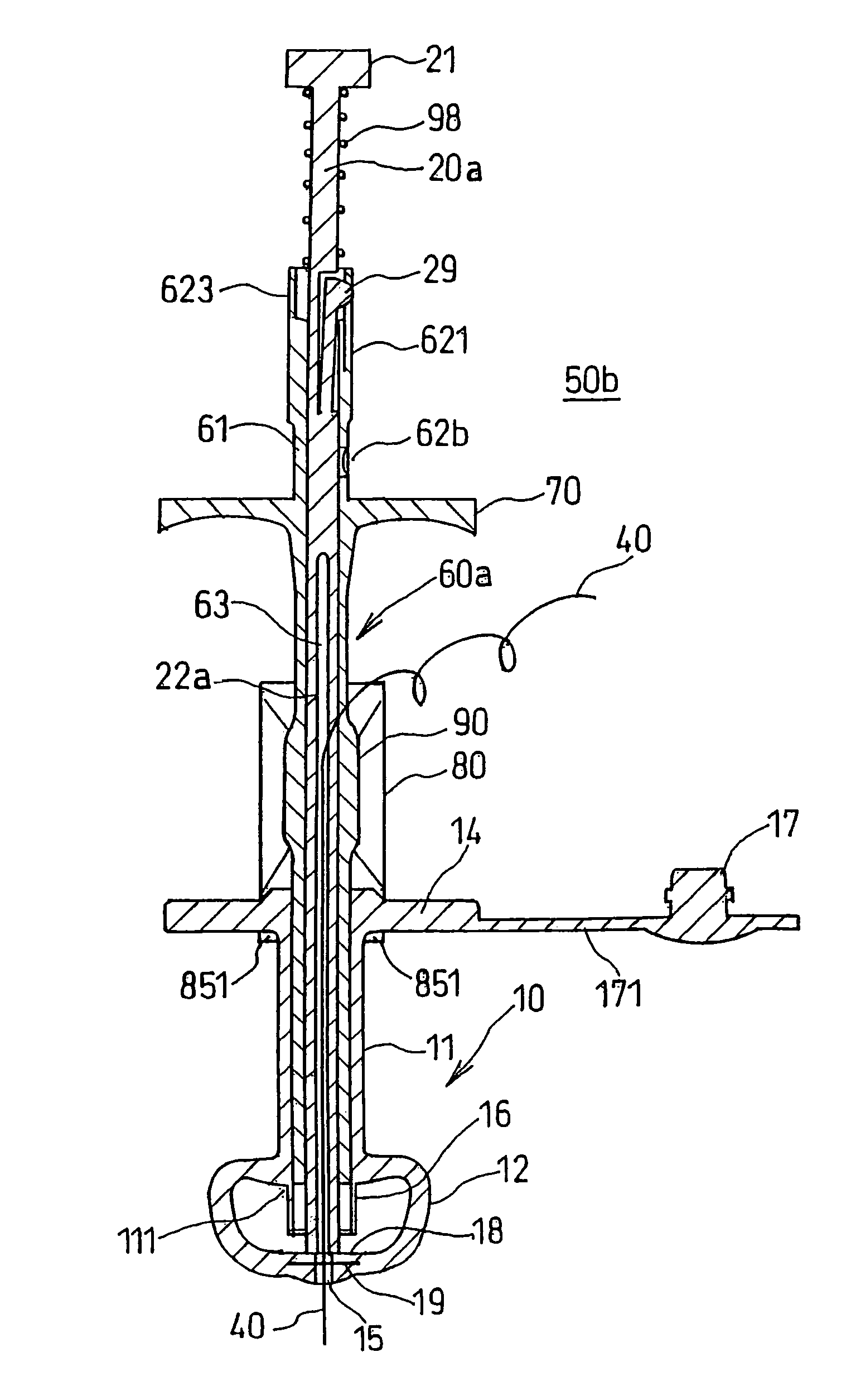
[0079]Then, the catheter kit for a fistula in a second embodiment will be explained by referring to FIG. 8 to FIG. 15. FIG. 8 (A) is a front view of an obturator used in the catheter kit of this example, FIG. 8 (B) is a right side view of FIG. 8 (A), FIG. 9 (A) is a view seen along a D-D line of FIG. 8, FIG. 9 (B) is a view seen along an E-E line of FIG. 8, FIG. 10 (A) is a front view of an external cylinder used in the catheter kit of this example, FIG. 10 (B) is a right side view of FIG. 10 (A), FIG. 11 (A) is a view seen along a F-F line of FIG. 10, FIG. 11 (B) is a view seen along a G-G line of FIG. 10, FIG. 12 is a schematic view of an assembly of the catheter kit of this example in the free state, FIG. 13 is an enlarged longitudinal cross-sectional view of FIG. 12, FIG. 14 is an enlarged schematic view of an assembly of the catheter kit of this example in the external force acting state, FIG. 15 is a view explaining the action of regulating tube deformation in the catheter kit...

third embodiment

[0093]Then, the catheter kit for a fistula in a third embodiment will be explained by referring to FIG. 17 to FIG. 20. FIG. 17 is a perspective of an external cylinder used in this example, FIG. 18 (A) is a front view of an external cylinder of FIG. 17, FIG. 18 (B) is a left side view of (A), FIG. 19 is a longitudinal cross-sectional view of an assembly of the catheter kit of this example in the free state, and FIG. 20 is a longitudinal cross-sectional view of an assembly of the catheter kit of this example in the external force acting state.

[0094]In the catheter kit for a fistula in the third embodiment shown in FIG. 17 to FIG. 20, same symbols are assigned to the same constitutional elements as those in FIG. 8 to FIG. 16, explanation thereof will be omitted, and different points will be mainly explained. That is, in the catheter kit in the third embodiment, main different points from the catheter kit of the second embodiment are that a finger hook and a stopper are provided on an ...


PUM


Abstract

A catheter kit for a burrow having a catheter and an obturator and excellent in operability. The catheter comprises a tube having, inside, a nutrient passage leading nutrition or chemicals from the outside of a body to the inside of a stomach and extending along the wall surface of the burrow and a non-balloon type endodwelling member fitted to the tip part of the tube, normally placed in an expanded state and reduced in diameter less than that in the expanded state when an external force acts thereon by the obturator, and indwelled in the stomach in a buried state in a living body. The obturator comprises a guide wire passage detachably engaged with the catheter and allowing a guide wire installed in the obturator ranging from the tip to the midway thereof to be inserted therein and an operation part for transmitting the external force to the endodwelling member fitted to the rear end thereof. The rear end part of the guide wire passage and the operation part are arranged in a separated state.

Description

TECHNICAL FIELD[0001]The present invention relates to a catheter kit for a fistula excellent in operability used in percutaneous endoscopic gastrostomy which is performed for the purpose of replenishing a nutritional supplement or a drug.BACKGROUND TECHNIQUE[0002]As a method of administering a nutrient to a patient who can not ingest a nutrient orally, generally, there are three administration methods of pervenous nutrient administration, stomach tube nutrient administration which is performed by inserting a nutrient tube into stomach or intestine nasally, and enteral nutrient administration though a gastric fistula. In recent years, with development of an enteral nutrient and a method of administering it, enteral nutritional management by percutaneous endoscopic gastrostomy (PEG) has been frequently performed. Since in PEG, a fistula is made by small operation, invasion is small as compared with surgical laparotomic gastrostomy, and a medical cost can be considerably reduced, there...

Claims


Application Information

Patent Timeline
Patent Type & Authority Patents(United States)
IPC IPC(8): A61M29/00A61J15/00
CPCA61J15/0015A61J15/0065A61J15/0038A61J15/0007
Inventor SUZUKISAKAGUCHI, YUKIHIKOARIKAWA, KIYOTAKAKOJO, YASUNORI
Owner YUTAKA SUZUKI
Why Eureka
Try Eureka