
Multi-function passive frequency mixer

a mixer and multi-functional technology, applied in the field of radio frequency telecommunications, can solve the problems of increasing noise power, consuming power, and poor linearity properties of active mixers, and achieves the effects of reducing the space required in the integrated circuit to perform these functions, good linearity, and good noise figur

Active Publication Date: 2009-12-08
WSOU INVESTMENTS LLC
View PDF31 Cites 16 Cited by
  • Summary
  • Abstract
  • Description
  • Claims
  • Application Information

AI Technical Summary

Benefits of technology

[0016]The invention provides several advantages. Firstly, the invention provides three functions with the same components. The invention functions as a frequency mixer, voltage multiplier, and low-pass filter and, therefore, the space required in an integrated circuit to perform these functions may be reduced. The invention provides a good linearity and a good noise figure at the same time, and it is particularly advantageous in multi-mode mobile phones which operate on several frequency bands. Previously, it has been difficult to design a bandpass filter to follow the low-noise amplifier due to the changing frequency bands. The invention does not require a separate bandpass filter between the low-noise amplifier and the frequency mixer, since it also operates as a low-pass filter and filters out the undesired frequency components that were filtered by the bandpass filter according to the conventional solution. Furthermore, since the invention multiplies the input voltage while it still is a passive component, i.e. does not consume power, the amplification of the low-noise amplifier may be reduced. This reduces the power consumption of the device utilizing the invention.

Problems solved by technology

On the other hand, the amplification results in an increased noise power, too.
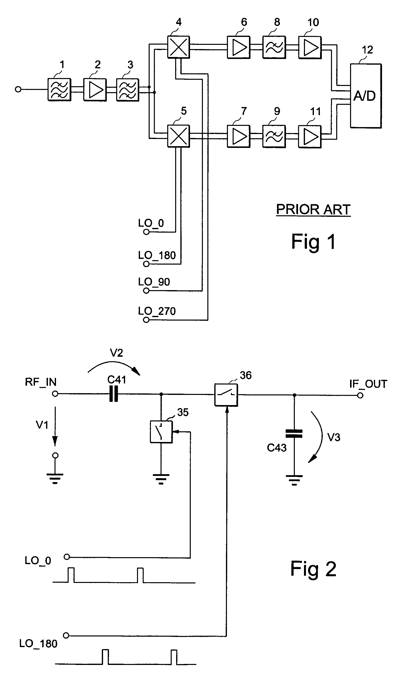
Additionally, linearity properties of the active mixers are generally quite poor, and the active mixers consume power which may be a limited resource in some implementations.
Their only drawback is that they attenuate the signal being mixed instead of amplifying it.
In this case, the level of the output signal of the amplifier 2 may rise so high that good linearity properties of the passive mixers are wasted.
As a consequence, the advantages of the passive mixers over the active mixers are also wasted.
Another problem related to the passive mixers is that designing a low-pass filter following a passive mixer may be difficult.
In CMOS implementations, it is hard to define the corner frequency of the filter accurately, since an output impedance of the mixer, the pulse ratio of a local oscillator and the tolerances of capacitance values of the mixer components affect the corner frequency.
Accordingly, the advantages of the passive mixer are wasted again.

Method used


Image

  • Multi-function passive frequency mixer
  • Multi-function passive frequency mixer
  • Multi-function passive frequency mixer

Examples


Embodiment Construction

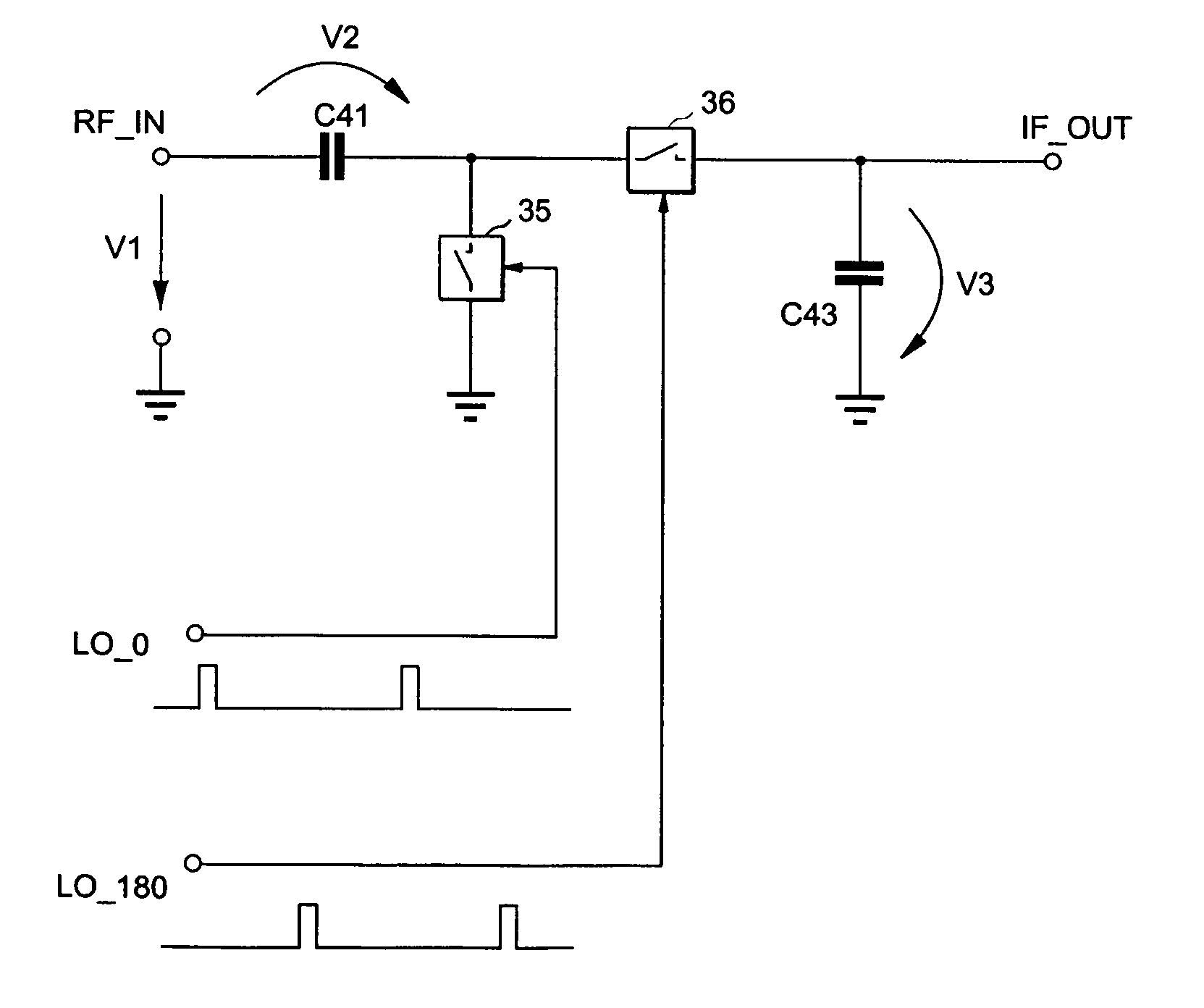
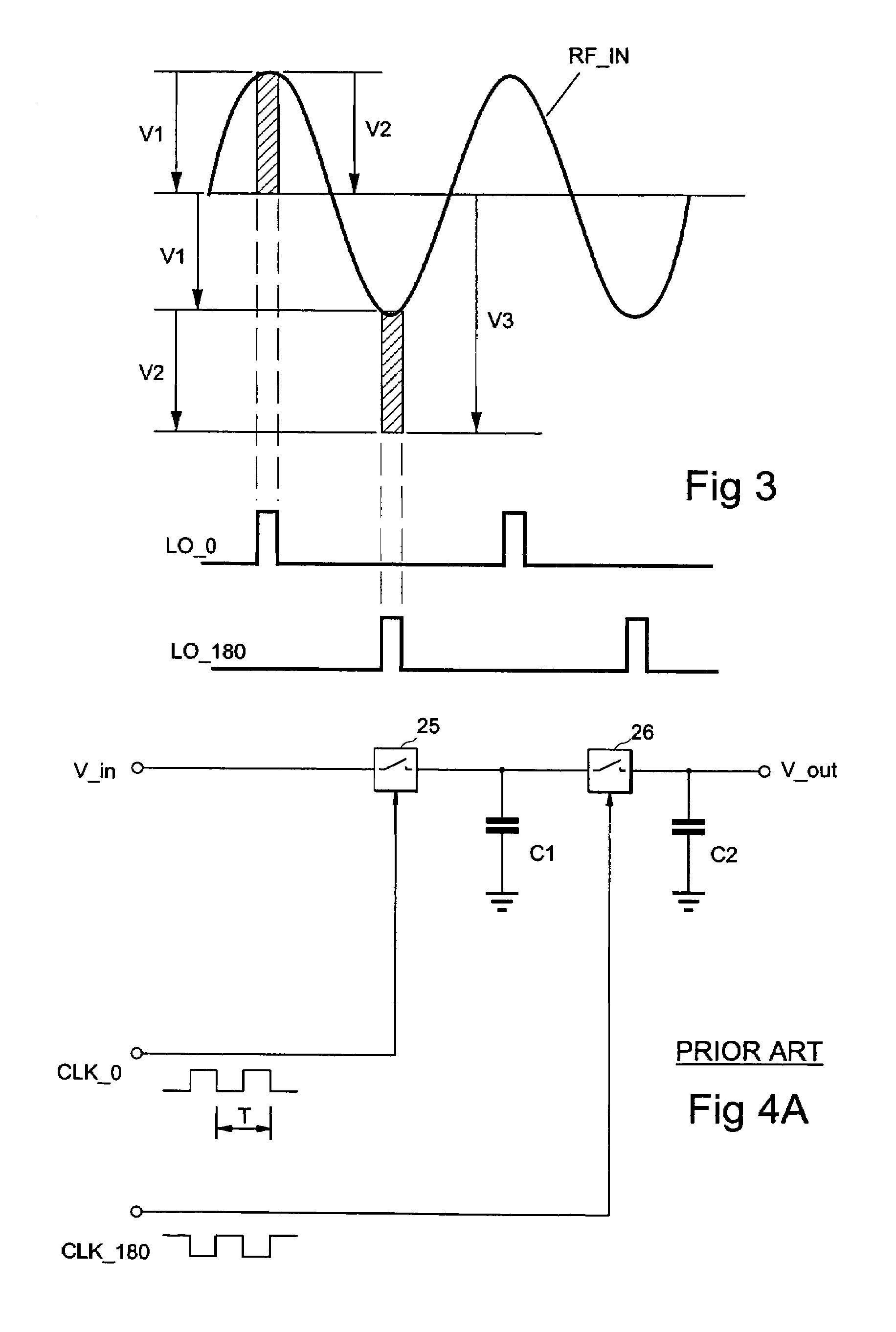
[0030]With reference to FIG. 2, let us examine an example of the frequency mixer according to an embodiment of the invention. The frequency mixer according to the embodiment of the invention functions as a frequency mixer, voltage multiplier, and a low-pass filter. The frequency mixer according to the embodiment of the invention is a passive mixer, i.e. it does not introduce additional power to the input signal. With proper utilization of passive components, the amplitude of an input signal may, however, be multiplied. The embodiment of the invention described with reference to FIG. 2 functions as a voltage doubler.

[0031]The frequency mixer has a radio frequency (RF) signal RF_IN as an input signal. The frequency mixer also receives two local oscillator signals LO_0 and LO_180 as input signals. The local oscillator signals may be square-wave signals provided by a local oscillator (not shown). The local oscillator signals may both have the same frequency which together with the cente...


PUM


Abstract

A frequency-mixing device performing voltage multiplying and low-pass filtering operations in addition to frequency mixing is provided. The three operations may be carried out with the same components by designing the frequency mixer appropriately. The frequency mixer comprises a first capacitance connected in series to the input of the frequency-mixing device, a first switch connected in parallel to the first capacitance, a second switch connected in series to the first capacitance, and a second capacitance connected in parallel to the second switching means. The switches are controlled by a local oscillator signal to close and open alternately according to a change in the voltage level of the first oscillator signal.

Description

FIELD[0001]The present invention relates generally to radio frequency telecommunications and particularly to passive radio frequency mixers.BACKGROUND[0002]Radio transceivers typically include a frequency mixer which converts a signal from a baseband to a radio frequency (RF) band or vice versa. The frequency mixer upconverts a transmission signal from the baseband to the RF band in transmission and / or downconverts a received signal from the RF band to the baseband in reception. Alternatively, the received RF signal may be converted to an intermediate frequency band in some implementations.[0003]The frequency mixer has a signal to be mixed, i.e. upconverted or downconverted, and one or more local oscillator signals as input signals, and it produces an output signal at a frequency which is a linear combination of the frequencies of the input signals. Typically, the local oscillator signals input to the frequency mixer are the same signal but with different phase shifts.[0004]The mixe...

Claims


Application Information

Patent Timeline
Patent Type & Authority Patents(United States)
IPC IPC(8): H04B15/00H04B1/26
CPCH03D7/1441H03D7/1458H03D7/165H03D7/1483H03D7/1466
Inventor VAISANEN, RISTO
Owner WSOU INVESTMENTS LLC
Learn More