Mounting structure of electrical equipment

a technology of mounting structure and electrical equipment, which is applied in the direction of battery/fuel cell control arrangement, cell components, battery capacity and battery lifetime reduction, etc., can solve the problems of reducing the space in the neighborhood of the toes of the rider on the rear seat, reducing the height of the rear seat, and reducing the mountability. , to achieve the effect of suppressing the height direction and favorable mounting

Inactive Publication Date: 2009-12-15
TOYOTA JIDOSHA KK
View PDF30 Cites 45 Cited by
  • Summary
  • Abstract
  • Description
  • Claims
  • Application Information

AI Technical Summary

Benefits of technology

[0011]In view of the foregoing, an object of the present invention is to provide a mounting structure of electrical equipment favorable in mountability while suppressing the dimension in height direction.
[0013]When a large-volume battery pack of an approximate rectangular parallelepiped configuration formed of nickel metal hydride batteries, for example, is to be mounted as electrical equipment on a vehicle in accordance with the present invention, the casing storing the battery pack (the battery pack and casing are referred to as battery assy) has an inclination in which the top side extends further towards the rear of vehicle than the bottom side at the rearward position of the vehicle. By virtue of the inclination, the battery assy, when mounted in the luggage room, will not become an obstacle during the loading and unloading of a spare tire (tempa spare wheel) that is disposed further backward than the battery assy. When the battery assy is mounted beneath the front seat, space is established around the toes of the rider on the rear seat by virtue of the inclination. The feet of the rider on the rear seat will not be obstructed by the battery assy. Inside the battery assy, space is established between the battery pack having the shape of a rectangular parallelepiped and the casing having an inclination. This space can be used as the chamber or channel of a cooling medium (air), so that the dimension in height direction will not be increased. As a result, a mounting structure of electrical equipment having further favorable mountability while suppressing the dimension in height direction can be provided.
[0023]Since the duct is formed of resin in the present invention, molding is facilitated. Further, when stress is generated at the battery pack due to collision or the like of the vehicle, the resin duct can absorb the stress to alleviate the impact on the battery pack, and to prevent shorting caused by contact between the casing (metal) and the terminal of the battery pack.
[0025]When viewed from the side of the vehicle in accordance with the present invention, a gap is formed that gradually expands from one end side to another end side at the top of the casing, whereas a gap is formed that gradually expands from the another end side towards the one end side at the bottom of the casing. When the cooling air flow is conducted from the upper side towards the lower side or from the lower side to the upper side of the battery pack, pressure loss can be suppressed to allow sufficient amount of cooling air up to the downstream side since the cross section of the conduit at the gap employed as a conduit gradually expands.
[0031]When viewed from the side of the vehicle in accordance with the present invention, a gap is formed that gradually expands from one end side to another end side at the top of the casing corresponding to an approximate parallelogram, whereas a gap is formed that gradually expands from the another end side towards the one end side at the bottom of the casing. When the cooling air flow is conducted from the upper side towards the lower side or from the lower side to the upper side of the battery pack, pressure loss can be suppressed to allow sufficient amount of cooling air up to the downstream side since the cross section of the conduit at the gap employed as a conduit gradually expands.
[0033]The present invention is advantageous in that there is no dead space, the spare tire can be loaded / unloaded without obstruction, and the feet of the rider on the rear seat is not obstructed even when the secondary battery, capacitor, fuel cell, and the like are accommodated.

Problems solved by technology

This generated heat will induce deficiency such as reduction in the battery capacity and battery lifetime if the generated heat is neglected.
This means that, when the battery module is mounted beneath the front seat, the space in the neighborhood of the toes of the rider on the rear seat may become smaller.
In the case where the battery module is mounted in the proximity of the rear wheel of a vehicle having two rows of seats, it may become an obstacle in taking out the spare tire stored in the recess provided at the floor panel.
Such a problem is not limited to a secondary battery, and is encountered common to secondary batteries (rechargeable batteries), capacitors, fuel cells, PCUs, and the like that require cooling by air or air circulation.

Method used


Image

  • Mounting structure of electrical equipment
  • Mounting structure of electrical equipment
  • Mounting structure of electrical equipment

Examples


Embodiment Construction

[0046]An embodiment of the present invention will be described hereinafter with reference to the drawings. In the following, corresponding components have the same reference characters allotted. Their designation and function are also identical. Therefore, details of the description thereof will not be repeated. Although the embodiment will be described based on a battery assy as the electrical equipment in the following, the electrical equipment may be a capacitor, fuel cell, PCU, or the like other than a battery assy. Furthermore, the type of battery in the battery pack constituting the battery assy may be, but is not particularly limited to, a lead storage battery, lithium-ion battery, and nickel metal hydride battery. In the following, a secondary battery (nickel metal hydride battery) is envisaged.

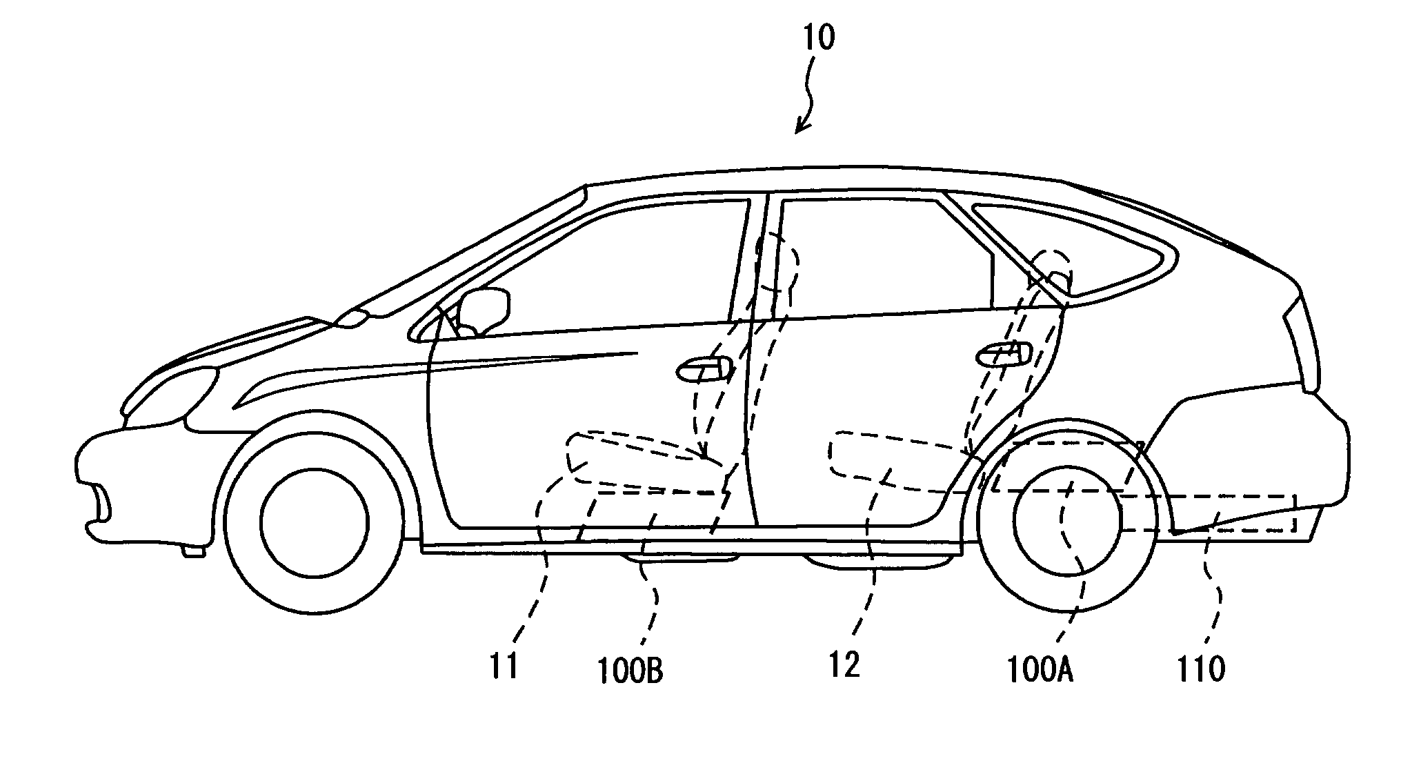
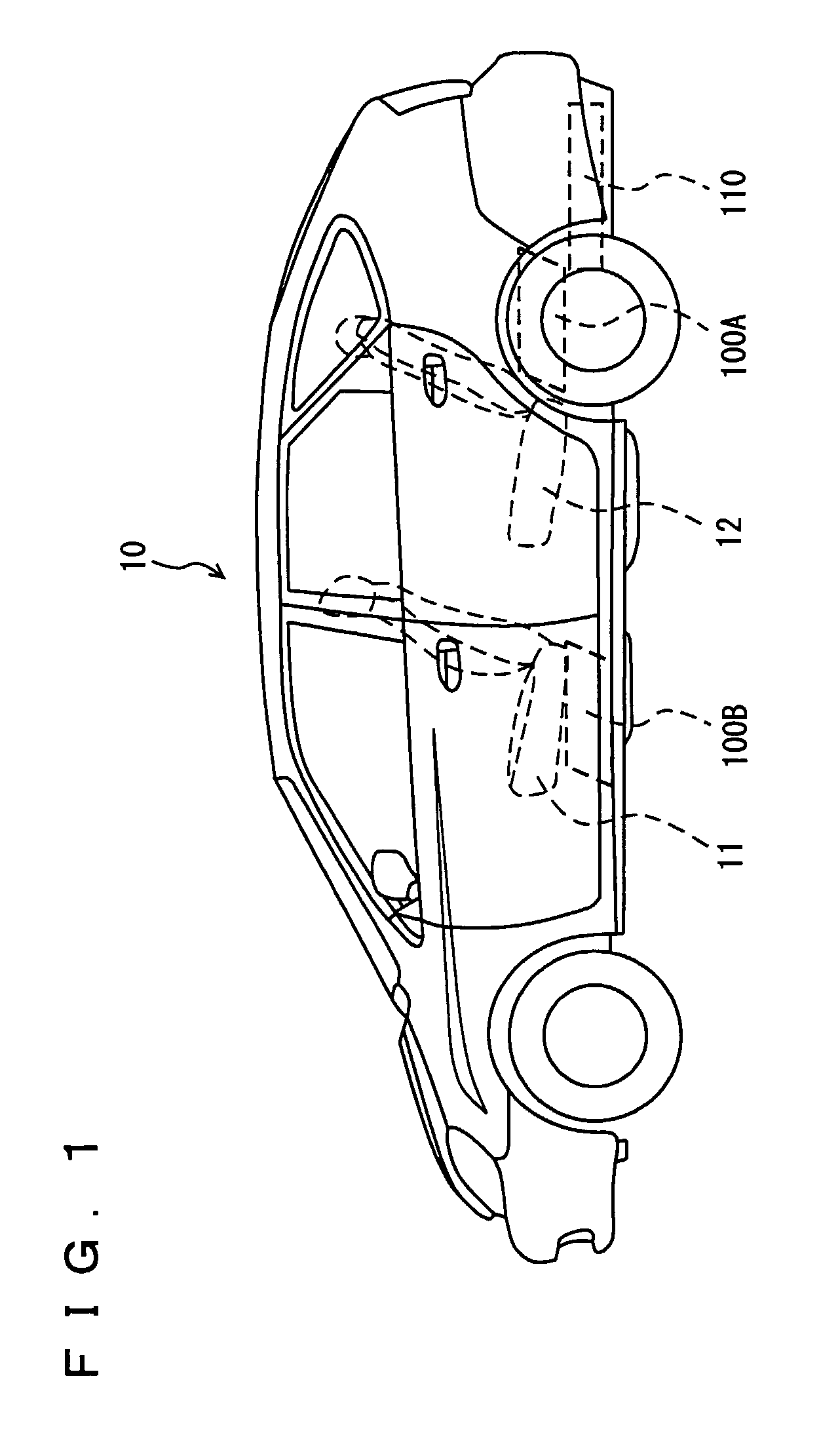
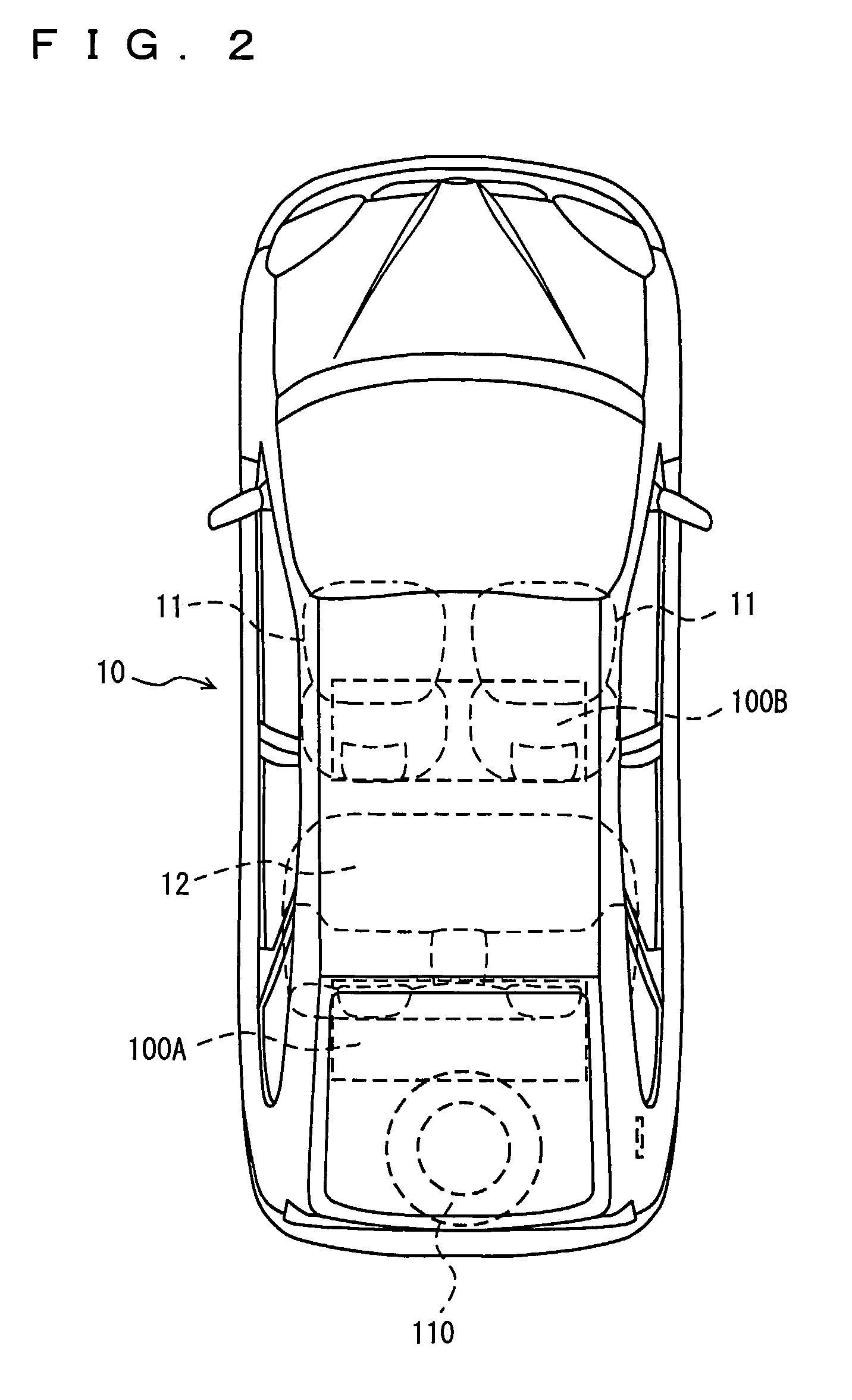
[0047]Referring to FIGS. 1 and 2, a vehicle 10 has a battery assy 100A mounted on the top surface of the luggage room floor, behind a rear seat 12, or a battery assy 100B mounted on t...


PUM

PropertyMeasurementUnit
output voltageaaaaaaaaaa
voltageaaaaaaaaaa
rated voltageaaaaaaaaaa

Abstract

A battery assy is mounted in a luggage room or beneath the rear seat. In the battery assy, a battery pack having a configuration of an approximate rectangle, when viewed from the side of the vehicle, is stored in an inclined manner in a casing formed of a battery cover and a lower case, having a configuration of an approximate parallelogram, when viewed from the side of the vehicle. A resin chamber is provided at a gap in the frontward position and the rearward position of the battery assy. A channel of cooling air is formed at a gap in the upper region and the lower region of the battery assy. The battery assy is mounted such that the bottom is protruding towards the front of the vehicle.

Description

TECHNICAL FIELD[0001]The present invention relates to electrical equipment (battery, capacitor, fuel cell, PCU (Power Control Unit) and the like) mounted on a vehicle, and more particularly, to the mounting structure of electrical equipment that requires cooling.BACKGROUND ART[0002]Vehicles of the type driven by a motor such as an electric car, a hybrid vehicle, a fuel cell vehicle and the like have a power supply unit including secondary batteries of relatively high capacity (battery pack) mounted. Such a battery pack obtains high voltage by the series connection of a plurality of batteries such as a lead storage battery, nickel metal hydride battery, lithium-ion battery, and the like.[0003]An assembly type secondary battery (battery module) is generally employed for a battery pack. A battery module is configured having a plurality of (for example, 6) electric cells (for example, a battery cell having an output voltage of 1.2V) linked integrally so as to obtain the required power c...

Claims


Application Information

Patent Timeline
Patent Type & Authority Patents(United States)
IPC IPC(8): B60R16/04B60K1/04B60K8/00B60K11/06B60R16/02H01M8/00H01M8/04H01M10/60H01M10/613H01M10/625H01M10/647H01M10/652H01M10/6556H01M10/6563H01M50/209H01M50/244H01M50/249
CPCB60K1/04H01M2/1083H01M8/04014H01M8/2475H01M10/5038H01M10/5073H01M10/5004B60K2001/005Y02T90/124H01M10/5067Y02E60/50H01M10/6563H01M10/652H01M10/6566H01M10/613B60L3/0046B60L58/26B60L50/66B60L50/64Y02T10/70Y02E60/10H01M50/249H01M50/209H01M50/244B60K2001/0422B60K2001/0416H01M2220/20H01M2250/20Y02T90/12
Inventor WATANABE, KO
Owner TOYOTA JIDOSHA KK
Why Eureka
Try Eureka