System and method for measuring cardiac output via thermal dilution using an implantable medical device with an external ultrasound power delivery system

Inactive Publication Date: 2009-12-15
PACESETTER INC
View PDF66 Cites 19 Cited by
  • Summary
  • Abstract
  • Description
  • Claims
  • Application Information

AI Technical Summary

Benefits of technology

[0013]The use of ultrasound to directly heat the heating element eliminates the need for a separate implantable power reception coil as may be required with an electromagnetic induction-based power delivery system and also eliminates the need for circuitry for routing power from the reception coil to the h

Problems solved by technology
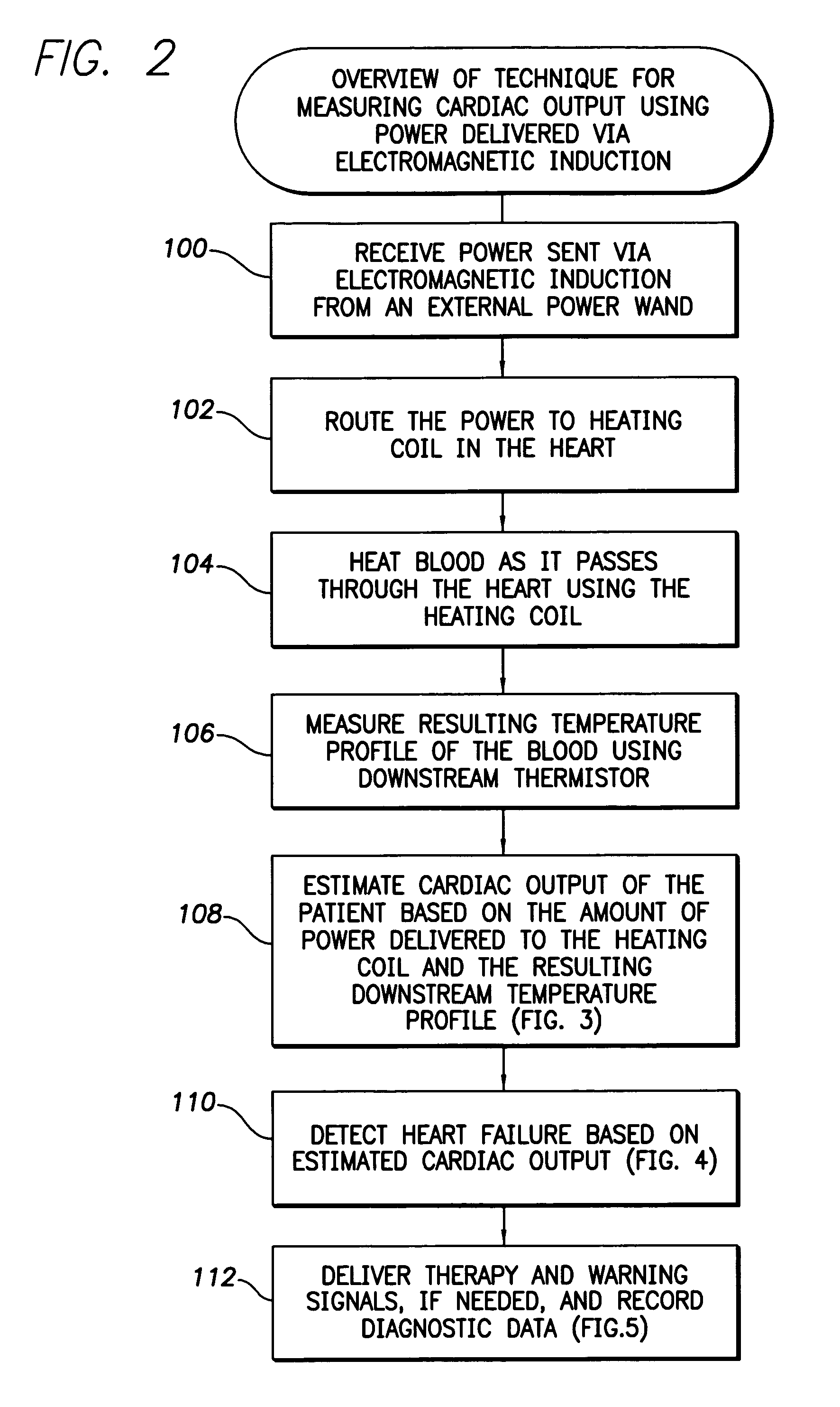
Heart failure is a debilitating disease in which abnormal function of the heart leads can result in blood flow that is insufficient to fulfill the needs of the tissues and organs of the body.
Typically, the heart loses propulsive power because the cardiac muscle loses capacity to stretch and contract.
Often, the ventricles do not adequately eject or fill with blood between heartbeats and the valves regulating blood flow become leaky, allowing regurgitation or back-flow of blood.
The impairment of arterial circulation deprives vital organs of oxygen and nutrients.
Fatigue, weakness and the inability to carry out daily tasks may result.
As heart failure progresses, it tends to become increasingly difficult to manage.
Even the compensatory responses it triggers in the body may themselves eventually complicate the clinical prognosis.
If the oxygen supply falls short of the growing demand, as it often does, further injury to the heart may result.
T

Method used


Image

  • System and method for measuring cardiac output via thermal dilution using an implantable medical device with an external ultrasound power delivery system
  • System and method for measuring cardiac output via thermal dilution using an implantable medical device with an external ultrasound power delivery system
  • System and method for measuring cardiac output via thermal dilution using an implantable medical device with an external ultrasound power delivery system

Examples


Embodiment Construction

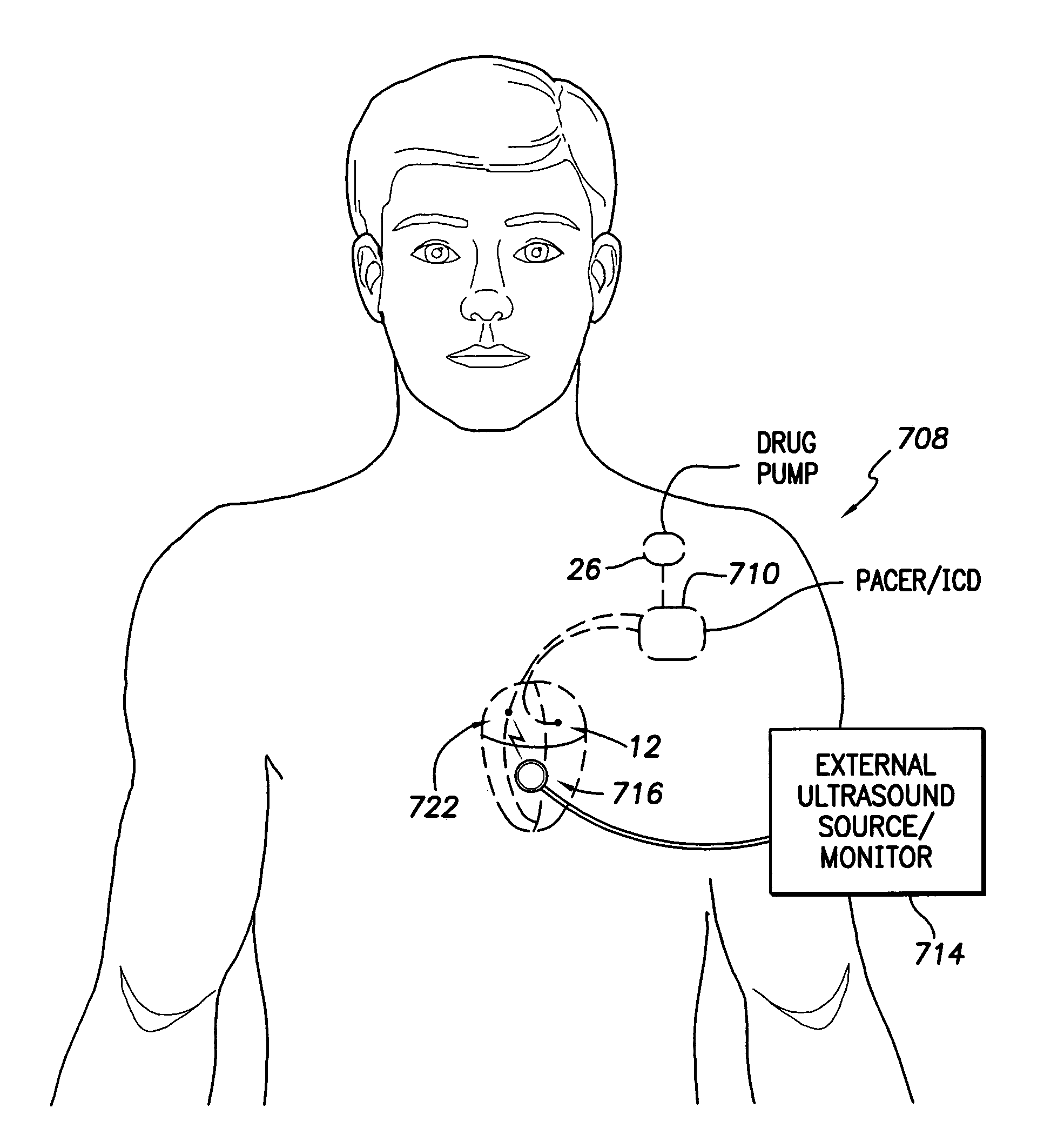
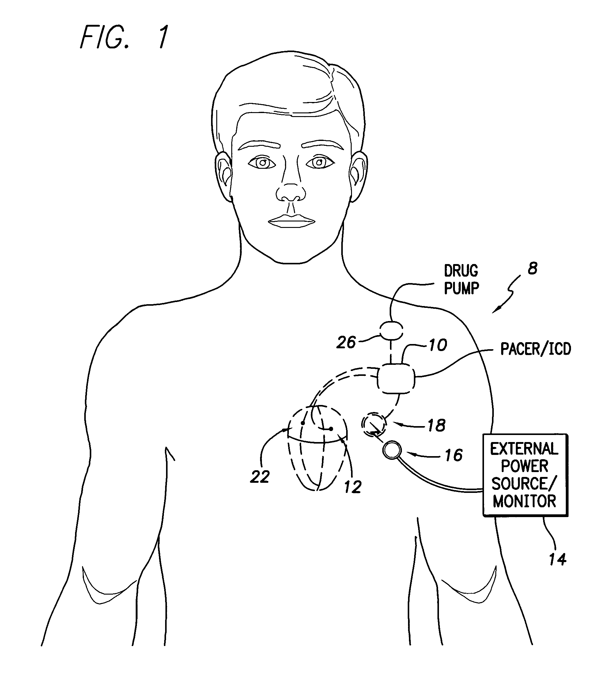
[0036]The following description includes the best mode presently contemplated for practicing the invention. This description is not to be taken in a limiting sense but is made merely to describe general principles of the invention. The scope of the invention should be ascertained with reference to the issued claims. In the description of the invention that follows, like numerals or reference designators will be used to refer to like parts or elements throughout. With reference to FIGS. 1-10, systems and methods for delivering power to an implantable system via electromagnetic induction for use in thermodilution analysis will be described. Then, with reference to FIGS. 11-17, systems and methods for delivering power to an implantable system via ultrasound for use in thermodilution analysis will be described.

[0037]Overview of Implantable System Using Electromagnetic Induction

[0038]FIG. 1 illustrates an implantable medical system 8 capable of estimating cardiac output via thermal dilut...


PUM


Abstract

The implantable device is capable of performing thermal dilution analysis of the cardiac output of a patient using power delivered from an external source. By using power from an external source, the implantable device conserves its power resources for other purposes, such as for pacing or defibrillation therapy. In one example, an external programmer or bedside monitor provides power through a hand-held power delivery wand via electromagnetic induction, with the power routed from a subcutaneous coil to a heating element implanted in the right atrium, which heats blood as it passes through the right atrium. In another example, the heating element is formed of a material that generates heat in response to a beam of ultrasound provided by the wand. In either case, a downstream blood temperature profile is detected using a thermistor implanted in the pulmonary artery and cardiac output is then estimated by analyzing the temperature profile.

Description

CROSS-REFERENCE TO RELATED APPLICATIONS[0001]This application is a continuation-in-part (CIP) of copending U.S. patent application Ser. No. 11 / 066,894, filed Feb. 25, 2005, entitled “System and Method for Measuring Cardiac Output Using an Implantable Medical Device,” which claims the benefit of U.S. Provisional Application No. 60 / 630,830, filed Nov. 24, 2004.FIELD OF THE INVENTION[0002]The invention generally relates to implantable medical devices, such as pacemakers or implantable cardioverter-defibrillators (ICDs), and in particular to techniques for measuring cardiac output via thermal dilution within a patient in which a medical device is implanted.BACKGROUND OF THE INVENTION[0003]Heart failure is a debilitating disease in which abnormal function of the heart leads can result in blood flow that is insufficient to fulfill the needs of the tissues and organs of the body. Typically, the heart loses propulsive power because the cardiac muscle loses capacity to stretch and contract. ...

Claims


Application Information

Patent Timeline
IPC IPC(8): A61B5/029A61B8/06A61B5/028
CPCA61B5/028A61B5/029A61N1/3655A61B2560/0214A61N1/3627A61B2560/0209
Inventor KARICHERLA, ANNAPURNAMIN, XIAOYIBOILEAU, PETERGILL, JONGBORNZIN, GENE A.
Owner PACESETTER INC
Why Eureka
Try Eureka