Detecting device and method of using same

Inactive Publication Date: 2009-12-15
1138037 ONTARIO ALIRT
View PDF71 Cites 14 Cited by
  • Summary
  • Abstract
  • Description
  • Claims
  • Application Information

AI Technical Summary

Benefits of technology

[0012]Most particularly, the device and method should reliably and accurately alert a driver when a target vehicle has either entered, or is within or exits a blind spot. The device should be able to provide alerts for blind spots on either one or on both sides of the vehicle, as desired. The device and method should just as reliably and accurately avoid false alarms, that is, alerts indicating that there is a vehicle in the blind spot when in fact the lane is clear. Further, it is desirable that the device and method's capacity to render accurate alerts and avoid false alarms remain effective for all practical variations in road, traffic, and weather conditions. This may include, for example, light and dark asphalt, smooth, bumpy, or pot-holed roads, light or heavy traffic, and the presence of sunlight, rain, snow, or ice on the road. As well, the device and method should operate effectively in the presence of shadows cast by nearby or overhead structures such as bridges and naturally occurring objects like trees.
[0013]It would be further advantageous for the device to be sufficiently versatile to be used with passenger cars as well as larger vehicles such as recreational vehicles and trucks. Yet another desirable feature would be for the device to be able to measure the absolute temperature of the road, so that warnings of potential black ice conditions could be provided to the driver.

Problems solved by technology

However, for simple reasons of geometry the mirrors that are commonly factory installed in motor vehicles only provide a partial view of the space immediately to the side and towards the back of the vehicle, which needs to be clear to change lanes.
While turning one's head can be a partially effective way to check the blind spot, it also creates a safety risk since it forces the driver to take his or her eyes away from the road directly in front of the vehicle.
In particular, there is a risk of a collision with a vehicle in the space ahead if that vehicle brakes or decelerates quickly in the moment that the driver is checking the blind spot.
Even if the driver does notice the vehicle in front when his eyes return, it may be too late to stop safely.
This risk becomes even more acute when driving conditions are less than optimal, such as in heavy traffic, or when there is poor visibility due to night time darkness or adverse weather conditions such as snow or ice on the road.
Further, there will always be drivers with limited or no head mobility due to disability or a stiff neck, as well as people with slower than average reaction times such as seniors.
Also, drivers of large vehicles such as trucks that sit high above the road may have difficulty seeing small vehicles occupying the lane on the passenger side.
Drivers operating under such conditions are much more susceptible to the risk of an accident when changing lanes.
Lastly, even with a shoulder check, portions of the field of view will be unviewable due to door pillars, condensation, snow, and the like.
Active devices such as this however are relatively complex and need both a transmitter and a receiver.
Because of the complexity of the components and the number of elements required, such as electrical connection, power supply, signal emitter, and signal detector, active systems tend to be expensive.
Further, failure of any one component means the whole system fails.
As well, such systems tend to create false positive alarms, due to reflection of the signal off of stationary objects such as parked cars and the like.
As a result, such systems have not been broadly commercially deployed.
However, this type of detector requires a change in temperature to create a detectable event and therefore is generally only effective when the target vehicle enters or leaves the field of view of the detector.
Target vehicles that are travelling at the same speed as the host vehicle or sensor platform and that remain in a fixed position in the blind spot may become undetectable.
A lane change in such a case could result in an accident.
This device however produces false alarms when there is a variation in road temperature between the reference spot and blind spot, such as the cool area created by a shadow under a bridge on a sunny day.
Thus, this prior device also suffers from a statistically small but unacceptably high level of false detection events.
In the absence of any solution that addresses the practical problems of detecting a target vehicle in a blind spot under real road, traffic, and weather conditions, tragic and costly accidents due to driver blind spot miscalculation will continue to occur.

Method used


Image

  • Detecting device and method of using same
  • Detecting device and method of using same
  • Detecting device and method of using same

Examples


Embodiment Construction

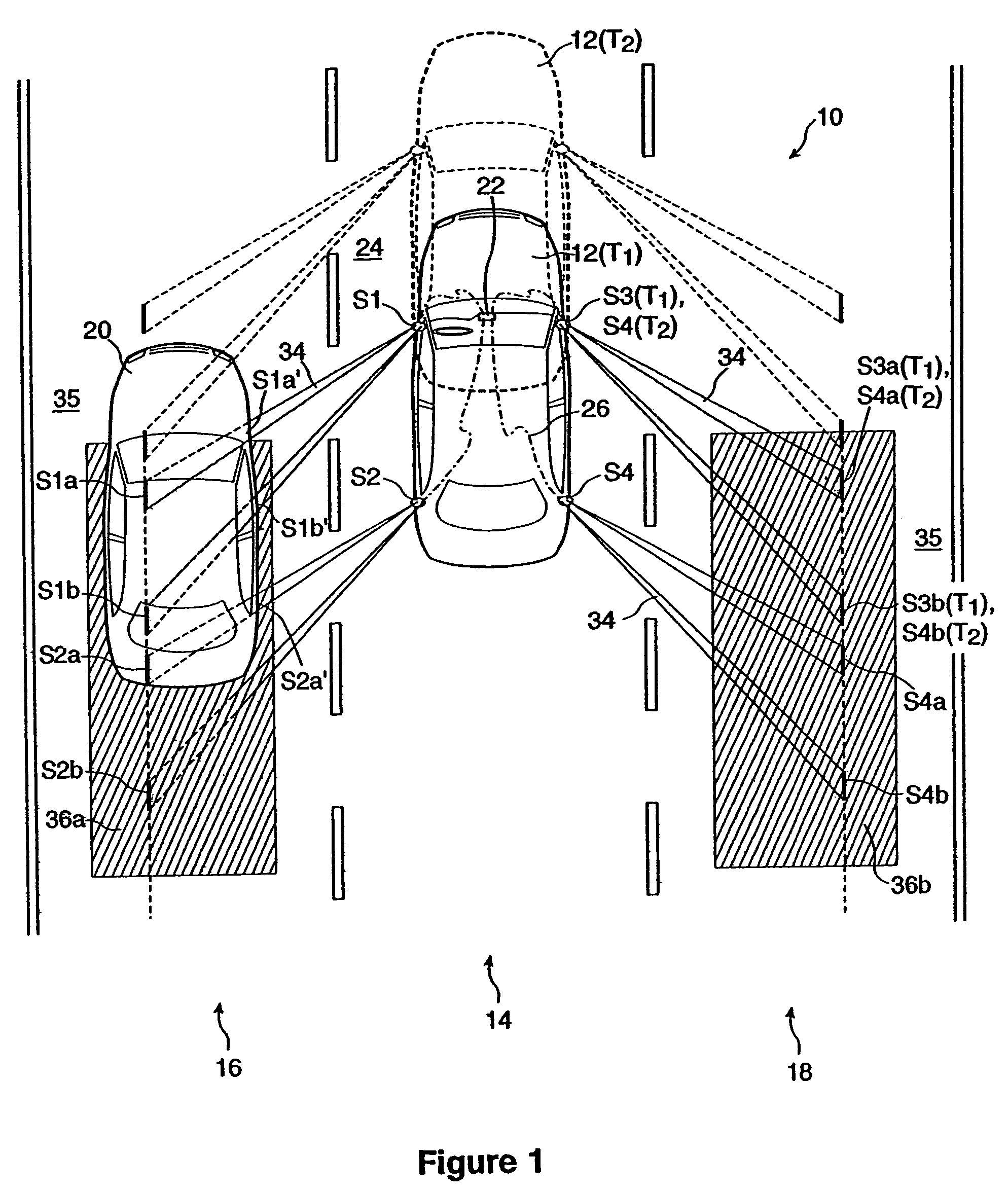
[0037]FIG. 1 shows a schematic view of the detecting device of the present invention being used in a representative driving environment on a road 10. The detecting device is shown installed in a host vehicle 12 being driven by a driver (not shown) in a center lane 14 of a 3-lane highway having a left lane 16 and a right lane 18. There is a target vehicle 20 in the left lane 16, and the right lane 18 is empty. In this specification the terms “moving” and “stationary” mean relative to a fixed point, such as a road surface. Thus, a moving host vehicle means a vehicle moving along a road surface, for example. A moving target vehicle means a vehicle moving along a road surface for example, and which may be moving faster, slower, or at the same speed as the host vehicle. Stationary means a fixed point, thus a stationary target area means a specific fixed location, for example, on a roadway.

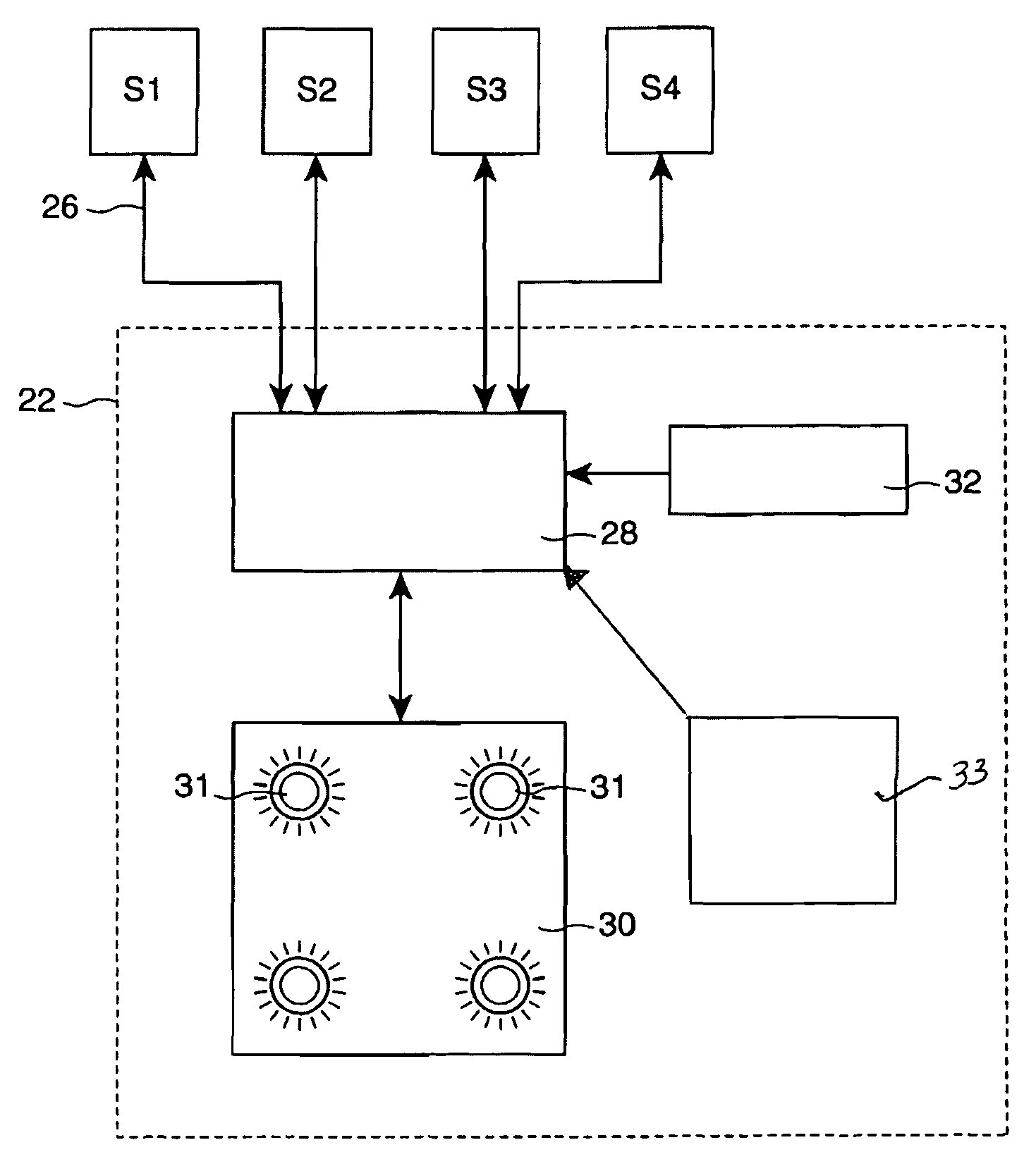
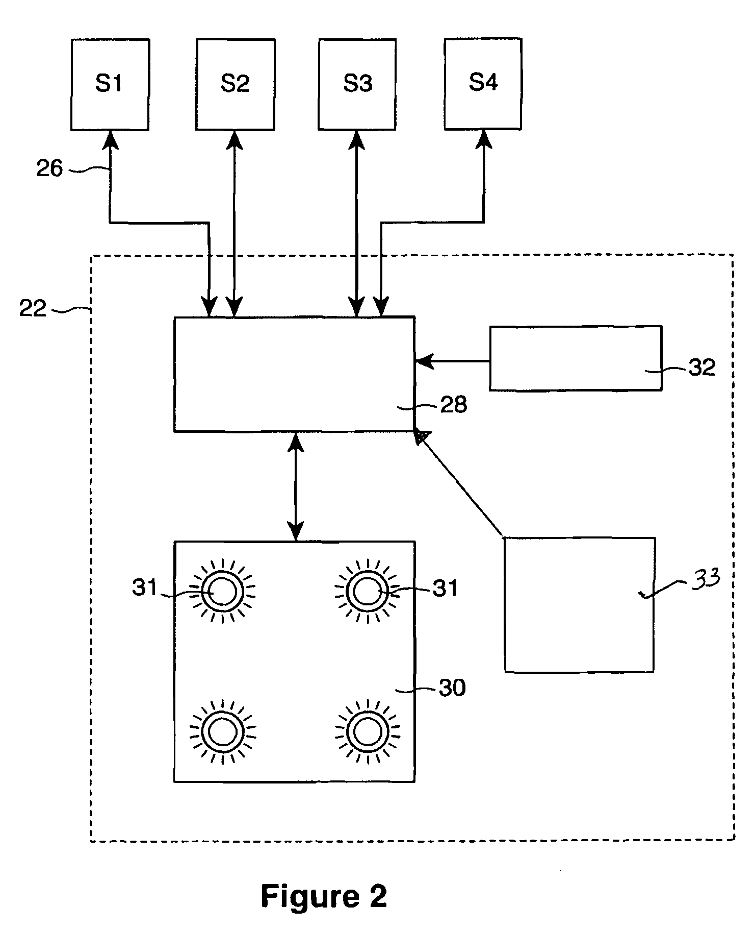
[0038]The detecting device comprises a control system or controller 22 and four detector means or de...


PUM


Abstract

A detecting device for detecting moving target vehicles from a moving host vehicle, comprising a first detector means mounted to the host vehicle and aligned to a stationary target area for generating at least a first output representative of the stationary target area at least at a time T1, a second detector means mounted to the host vehicle and aligned to the stationary target area for generating at least a second output representative of the stationary target area at least at a time T2, and a control system to receive the first and second outputs and to compare the first output at T1 to the second output at T2 to identify any differences between the outputs, whereby a target vehicle moving in the stationary target area may be detected.

Description

CROSS-REFERENCE TO RELATED APPLICATION[0001]This application is a continuation of U.S. application Ser. No. 09 / 799,664, filed on Mar. 7, 2001 now U.S. Pat. No. 6,753,766, the contents all of which are incorporated herein by reference.FIELD OF THE INVENTION[0002]This invention relates generally to the field of detecting devices, and more particularly to devices capable of detecting objects, for example, in a vehicle operator's blind spot.BACKGROUND OF THE INVENTION[0003]Motor vehicle drivers are required to negotiate traffic safely when travelling on public roads. For this reason, cars, trucks and other road-travelling motor vehicles are typically equipped with mirrors positioned both inside and outside the vehicle. The mirrors allow the driver to see a portion of the road behind or beside the vehicle with only a slight shift of the eyes or turn of the head. If other vehicles are visible the driver will be suitably alerted and in position to avoid making an inappropriate move, such a...

Claims


Application Information

Patent Timeline
IPC IPC(8): G08G1/16B60T17/22G01S13/93
CPCB60T17/22G01S2013/9332G01S2013/9315
Inventor PATCHELL, JOHN W.
Owner 1138037 ONTARIO ALIRT
Why Eureka
Try Eureka