Relating to well head separators

a technology of hydrocyclone separator and well head, which is applied in the direction of water/sludge/sewage treatment, fluid removal, centrifugal force sediment separation, etc., can solve the problems achieve the effect of economising on manufacturing costs, simple shapes and amenability

Active Publication Date: 2009-12-22
AXSIA SERCK BAKER
View PDF17 Cites 14 Cited by
  • Summary
  • Abstract
  • Description
  • Claims
  • Application Information

AI Technical Summary

Benefits of technology

[0015]With this arrangement the segments can have very simple shapes which make them amenable to being made in hard wearing materials. Also as each segment may be manufactured separately to the others, segments which endure less abrasion than others may even be made of a different material, thereby economising on manufacturing costs. Furthermore, whether each segment is made of the same material or not, segments which have worn too much may simply be replaced, rather than having to replace the entire separator tube as is traditionally required.
[0016]In another aspect, the invention also provides a cyclone separator assembly having an inlet for directing fluids and particulates into an inlet chamber prior to being directed to the inlet end of a cyclone separator tube, the overflow outlet of the separator assembly initially being disposed centrally within the inlet chamber and being surrounded by a collar acting as an anvil for receiving fluid and particulates initially directed thereagainst by the inlet, the arrangement being such that the particulates impinge upon the collar in preference to the side walls of the inlet chamber, thereby obviating the problem of the side walls of the inlet chamber being substantially worn by the particulates initially impinging directly onto the side walls.
[0017]With this arrangement, instead of the inlet being arranged substantially tangentially so as to introduce fluid and particulates into the cylindrical portion of the hydrocyclone in a substantially straight line, it is instead initially directed towards the axis of the separator tube such that after particulates impinge upon the collar their kinetic energy is considerably reduced such that when they thereafter enter the inlet of the cyclone tube their velocity is well below that which they had in the separator vessel inlet port. In turn, this has the additional advantage in ensuring that such particulates are less likely to cause severe abrasion as they pass through the cyclone tube and underflow outlet end.
[0019]The cyclone separator assembly may conveniently have an inlet port into the inlet chamber which is inclined relative to the major axis of the separator tube and an overflow outlet exit port which is also inclined relative to the major axis of the separator tube, whereas conventionally the inlet and the overflow outlet are at right angles to the major axis of the separator tube. This has the advantage of enabling the separator assembly to fit in a confined space in which access to the inlet and outlet is limited.

Problems solved by technology

Also as each segment may be manufactured separately to the others, segments which endure less abrasion than others may even be made of a different material, thereby economising on manufacturing costs.

Method used


Image

  • Relating to well head separators
  • Relating to well head separators
  • Relating to well head separators

Examples


Embodiment Construction

[0023]While this invention is susceptible of embodiments in many different forms, there is shown in the drawings and will herein be described in detail preferred embodiments of the invention with the understanding that the present disclosure is to be considered as an exemplification of the principles of the invention and is not intended to limit the broad aspect of the invention to the embodiments illustrated.

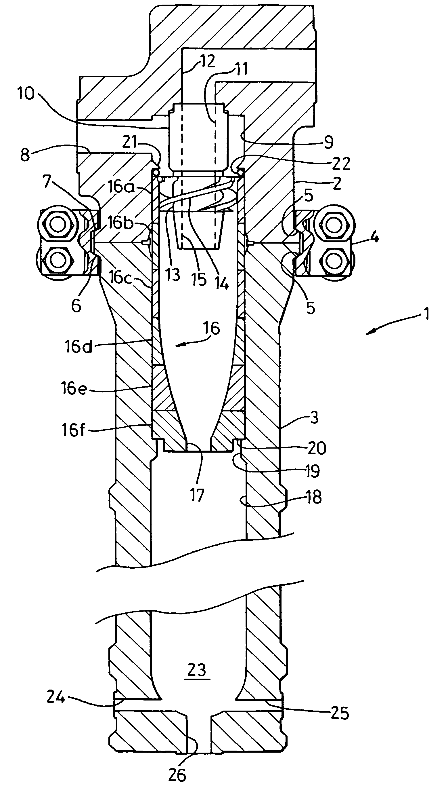
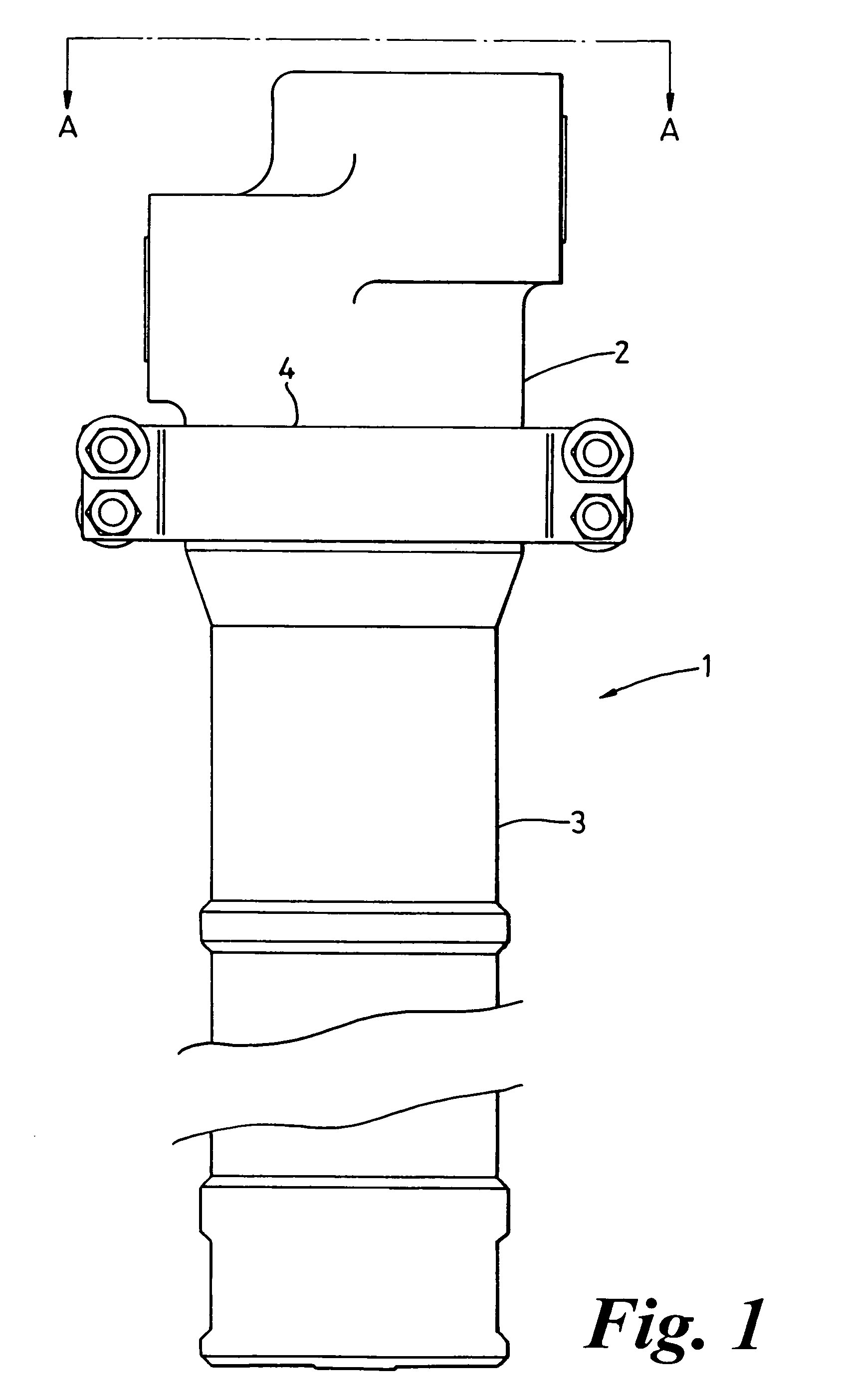
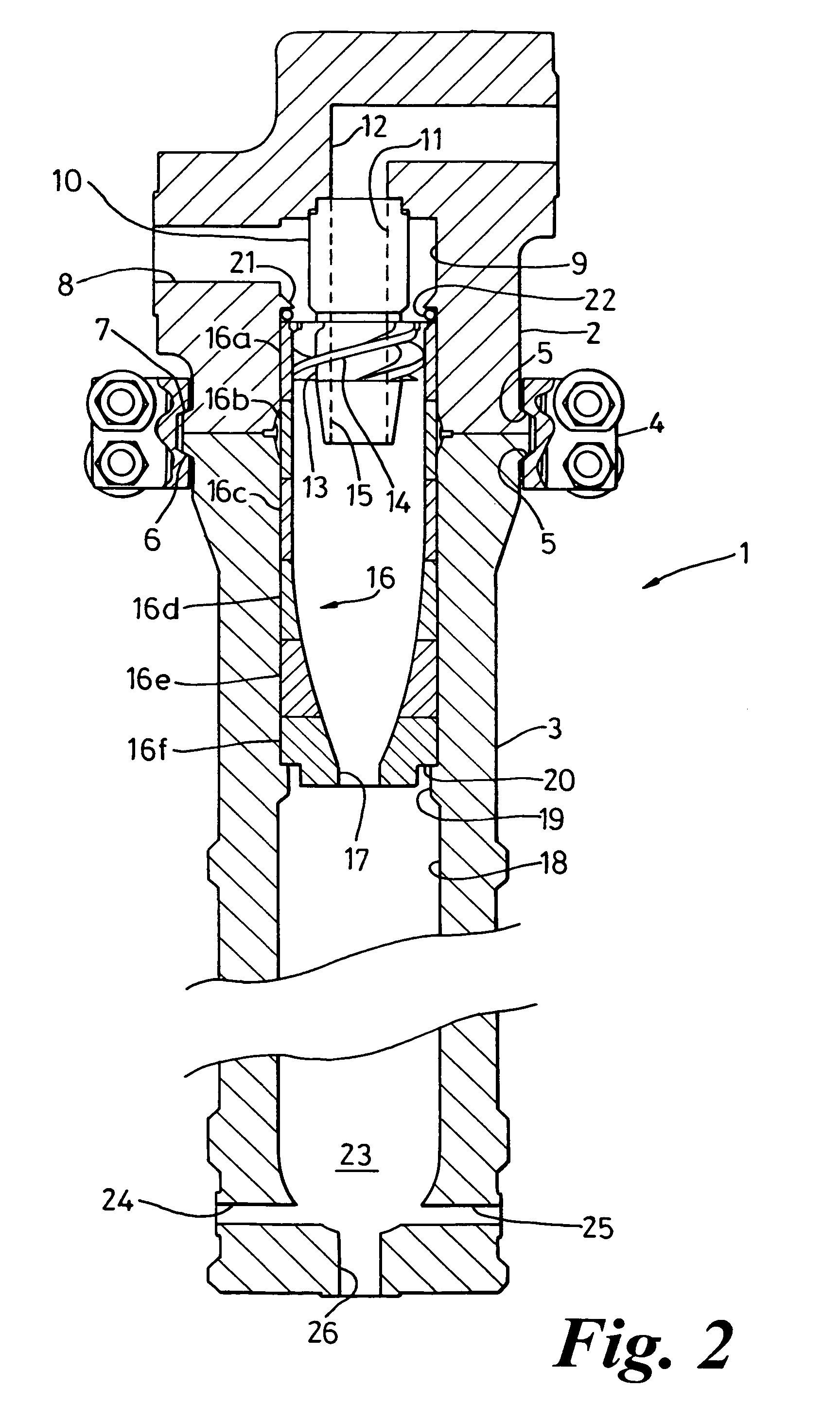
[0024]Referring to the Figures, a cyclone separator assembly according to this embodiment of the invention comprises a generally cylindrical housing 1 having upper and lower halves 2, 3 secured together by a generally annular two-part clamp 4 having internally disposed inclined cam surfaces 5 co-operable with correspondingly-shaped cam surfaces 6 / 7 (shown in FIG. 2) around the flanged periphery of each half of the housing 2, 3 in the region where they abut each other.

[0025]As shown with reference to FIG. 2, in the, upper, housing half 2 is a fluid inlet 8 for directing fluid an...


PUM

PropertyMeasurementUnit
sizeaaaaaaaaaa
pressuresaaaaaaaaaa
pressuresaaaaaaaaaa

Abstract

Well head hydrocyclone separators are typically used for separating particulates from fluids such as gas, oil and water and mixtures thereof. Well head separators are useful to prevent wear and blocking of choke valves, rupture of piping, damage to instruments and to prevent vessels from filling with particulate materials. In the present invention, the cyclone separator assembly includes an inlet, an overflow outlet and a segmented cyclone separator tube.

Description

CROSS-REFERENCE TO RELATED APPLICATIONS[0001]This application claims priority from British Appln. No. 0409230.0, filed Apr. 26, 2004, and incorporated herein by reference. The application also claims priority from U.S. Provisional Ser. No. 60 / 572,436, filed May 19, 2004, incorporated herein by reference.FEDERALLY SPONSORED RESEARCH OR DEVELOPMENT[0002]Not applicable.TECHNICAL FIELD[0003]The invention relates to well head hydrocyclone separators which are typically used for separating particulates from fluids such as gas, oil and water and mixtures thereof.BACKGROUND OF THE INVENTION[0004]The primary reasons for using wellhead separators are to prevent wear and blockage of choke valves, to prevent wear and subsequent rupture of piping, to prevent damage and malfunction of instruments, and to prevent vessels filling with the particulate materials. The wellhead separation duty can include the requirement to separate particles up to 12 to 25 mm in size, and to separate hard abrasive par...

Claims


Application Information

Patent Timeline
Patent Type & Authority Patents(United States)
IPC IPC(8): B01D21/26B04C5/085B04C5/08C02F1/38E21B43/34E21B43/36
CPCB04C5/08E21B43/34C02F1/38B04C5/085E21B43/35
Inventor MILDREN, RICHARD TREVELANGE, NEVILLE ERNEST
Owner AXSIA SERCK BAKER
Why Eureka
Try Eureka