Eureka AIR delivers breakthrough ideas for toughest innovation challenges, trusted by R&D personnel around the world.

Thinners for invert emulsions

Inactive Publication Date: 2009-12-29
HALLIBURTON ENERGY SERVICES INC
View PDF175 Cites 10 Cited by
  • Summary
  • Abstract
  • Description
  • Claims
  • Application Information

AI Technical Summary

Benefits of technology

[0011]According to the method of the present invention, at least one compound or composition is added to a water-in-oil or invert emulsion, or a drilling fluid or well service fluid comprising such emulsion, which reduces the viscosity of the emulsion over a broad temperature range or which enables or enhances the ability of the emulsion to maintain its viscosity over a broad temperature range. The compound or composition, which may be generally called a “thinner,” continues to have this effect in a drilling fluid or well service fluid comprising the emulsion for use in drilling or servicing wellbores in subterranean formations, particularly hydrocarbon bearing subterranean formations, over a broad temperature range. The first such thinner compound of the present invention is a non-ionic surfactant which is a reaction product of ethylene oxide, propylene oxide and / or butylene oxide with C10 carboxylic acids or C10-22 carboxylic acid derivatives containing at least one double bond in position 9 / 10 and / or 13 / 14 having units of the general formula:

Problems solved by technology

However, increased viscosity can result in problematic sticking of the drill string, and increased circulating pressures can contribute to lost circulation problems.
Although such compounds have been shown to effect thinning of drilling fluids, their effectiveness as thinners is not always uniform over the entire range of temperatures (typically as low as about 40° F.

Method used


Image

  • Thinners for invert emulsions
  • Thinners for invert emulsions
  • Thinners for invert emulsions

Examples


examples

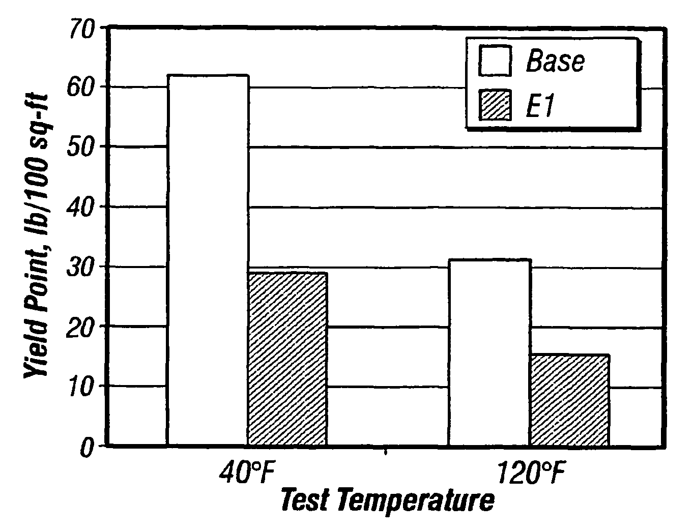
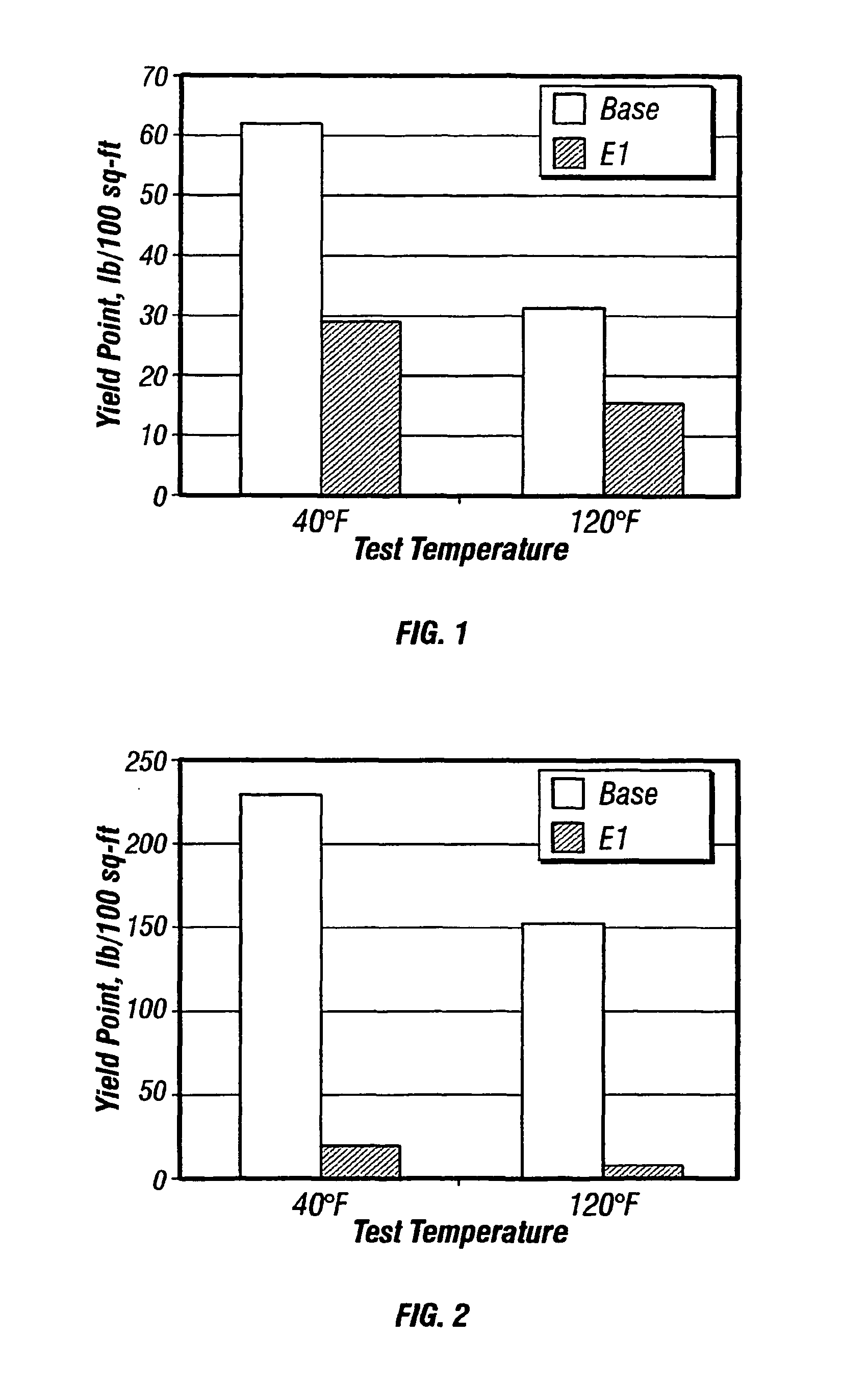
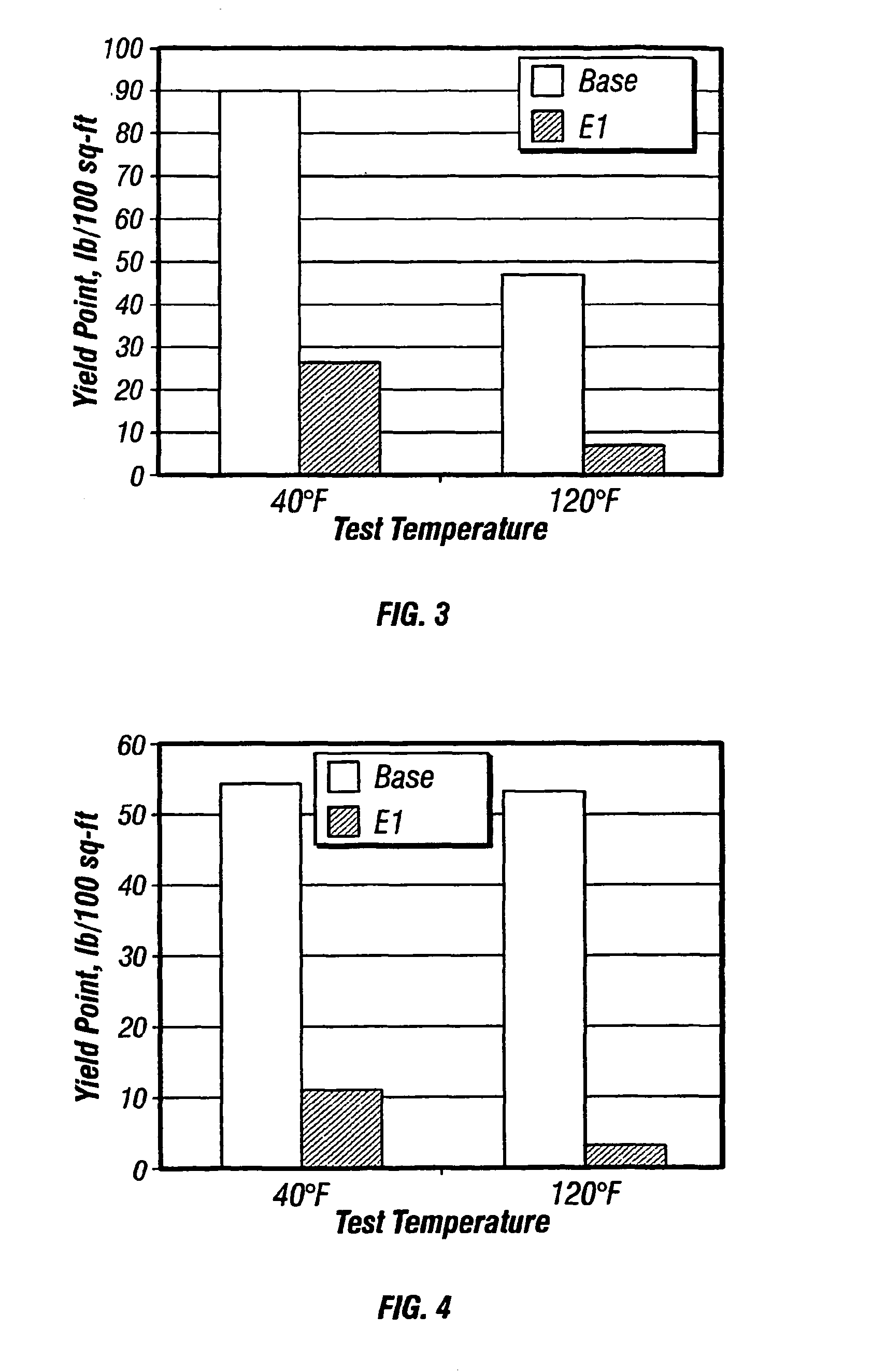
[0077]To show the effect of the invention, the following experiments were conducted. In each case an invert emulsion drilling mud system of the following general composition was prepared:

[0078]

EsterBbl0.496Waterbbl0.233Emulsifierlb6.0Organophilic bentonitelb1.0Organophilic lignitelb5.0Alkali reserve (lime)lb1.5CaCl2 × 2 H2Olb27.2Baritelb314.0Rev. dustlb45.5Dispersing auxiliarylb0.5Thinnerlb / bbl3.0

[0079]The oil phase (A) used was a 2-ethylhexyl octanoate as disclosed in EP 0 386 636. The emulsifier used was the product EZ MUL NTE (Baroid Drilling Fluids Inc., Houston, Tex.). The oil / water ratio was 70 / 30 in each case. Measurements were carried out on a system without thinner (C1), and with four non-ionic surfactant thinners E1 to E4 of the invention.

[0080]

E1RS1100 ™, of Cognis, Germany, see belowE2like E1, but reacted with 39 parts of ethylene oxideE3like E1, but reacted with no parts of ethylene oxideE4like E3, but reacted with 25 parts of ethylene oxideE5like E1, but reacted with 5...


PUM

PropertyMeasurementUnit
Temperatureaaaaaaaaaa

Abstract

A method of reducing the viscosity of invert emulsions and oil-based drilling fluids and well service fluids comprising such emulsions over a broad temperature range is disclosed. The method comprises adding to said invert emulsions of the invention a non-ionic surfactant alone or in combination with a co-thinner having the formula: R″″—(C2H4O)n(C3H6O)m(C4H8O)k—H where R″″ is a saturated or unsaturated, linear or branched, alkyl radical having about 8 to about 24 carbon atoms, n is a number ranging from about 1 to about 10, m is a number ranging from about 0 to about 10, and k is a number ranging from about 0 to about 10. The non-ionic surfactant is a reaction product of ethylene oxide, propylene oxide and / or butylene oxide with C10-22 carboxylic acids or C10-22 carboxylic acid derivatives containing at least in position 9 / 10 and / or 13 / 14 structural units of general formula (I) where R1 is a hydrogen atom or an OH group or a group OR2. R2 is an alkyl group of about 1 to about 18 carbon atoms, an alkenyl group of about 2 to about 18 carbons atoms, or a group of the formula (II): R3 is a hydrogen atom, an alkyl group of about 1 to about 21 carbon atoms or an alkylene group or 2 to 21 carbon atoms.

Description

BACKGROUND OF THE INVENTION[0001]1. Field of the Invention[0002]This invention is generally related to methods and compositions for drilling and servicing wellbores in hydrocarbon bearing subterranean formations. Particularly, this invention is related to oil-based drilling fluid systems comprising water-in-oil invert emulsions, and to thinners that enhance or enable use of such fluids over a broad temperature range.[0003]2. Description of Relevant Art[0004]A drilling fluid, or “mud” which a drilling fluid is also often called, is a specially designed fluid that is circulated in a wellbore as the wellbore is being drilled to facilitate the drilling operation. The various functions of a drilling fluid include removing drill cuttings from the wellbore, cooling and lubricating the drill bit, aiding in support of the drill pipe and drill bit, and providing a hydrostatic head to maintain the integrity of the wellbore walls and prevent well blowouts. Specific drilling fluid systems are se...

Claims


Application Information

Patent Timeline
IPC IPC(8): C09K8/00C09K8/36C09K23/00
CPCC09K8/36
Inventor MUELLER, HEINZKIRSNER, JEFFBURROWS, KIMBERLY
Owner HALLIBURTON ENERGY SERVICES INC
Why Eureka
Eureka Blog
Learn More