
Bending wave panel loudspeaker

a loudspeaker and bending wave technology, applied in the direction of diaphragm construction, transducer diaphragms, electromechanical transducers, etc., can solve the problem that the excitation method occupies a proportion of the overall panel area

Active Publication Date: 2009-12-29
GOOGLE LLC
View PDF10 Cites 36 Cited by
  • Summary
  • Abstract
  • Description
  • Claims
  • Application Information

AI Technical Summary

Benefits of technology

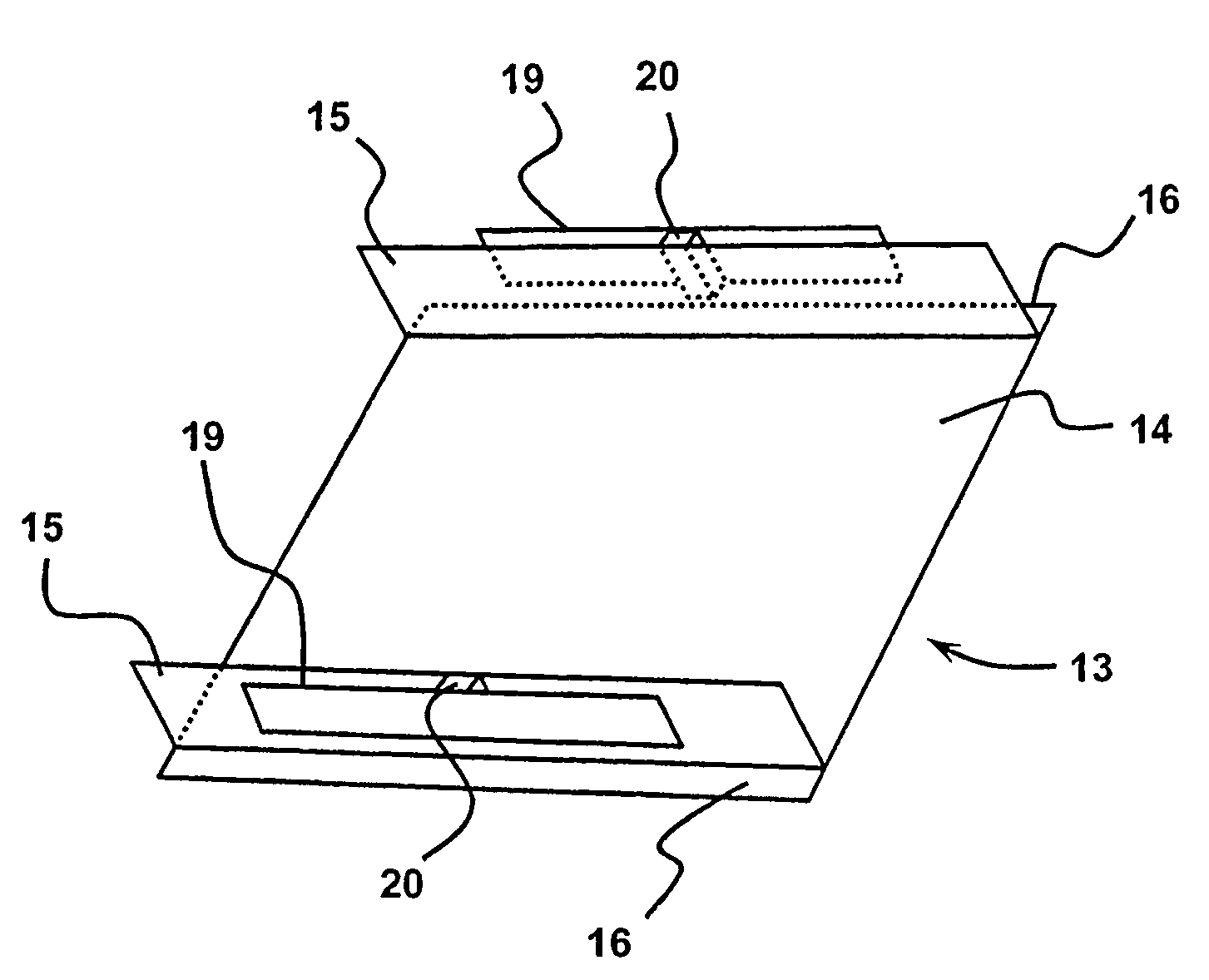
[0031]The bending wave panel may be freely supported along its edge or edges having an associated lever or flange. The suspension may be generally or locally adapted to provide boundary conditions which improve the performance. Such adaptations may aid modal density and / or adjust modal distribution. The lever coupler may have selected parameters chosen to add beneficial modes to the coupled system. The panel may have a curved profile, either simple or complex. The curvature may be selected with regard to stiffness and thickness of the panel to improve the performance.
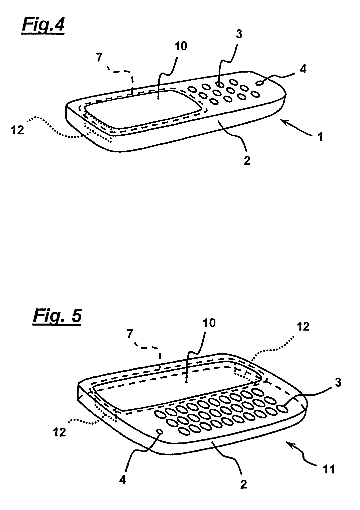
[0037]Space is at a premium in small electronic devices and technology solutions which reduce the space requirements and integrate functions into sub assemblies are highly valued. The solution of the present invention allows one or more signal channels. For example, stereo, two channel reproduction has substantial market value and performance may be enhanced for such small devices by the well known and various systems for signal processing to increase the perceived spatial effects in the reproduced sound. More than one sound channel and related channel exciter may be used to drive the panel diaphragm, e.g. using an opposed pair of levers on opposite edges of the panel. The channels may be electrically combined at lower frequencies where there is common information, to increase efficiency. The channels so combined may be kept separated at higher frequencies to maintain the spatial and perceived channel separation effects in the reproduced sound.
[0038]The invention provides a means to allow the maximum viewable area on a mobile communications device or PDA and permit stereo signal reproduction. The goal is 100% viewable area. At the same time it is an objective to allow a multi-channel signal to be reproduced without the expected loss of viewable area due to additional take-up of otherwise available display area caused by the requirement for more than one transducer.
[0040]It is an object of the invention to provide stereo at an effective cost. This is achieved by integrating two or more signal channels into one loudspeaker assembly. This may have the additional advantage of one connector. The loudspeaker assembly may be further integrated with the display module, so as to minimise assembly time and cost.

Problems solved by technology

This excitation method unfortunately occupies a proportion of the overall panel area, see for example International Application WO00 / 02417 to the present applicants.

Method used


Image

  • Bending wave panel loudspeaker
  • Bending wave panel loudspeaker
  • Bending wave panel loudspeaker

Examples


Embodiment Construction

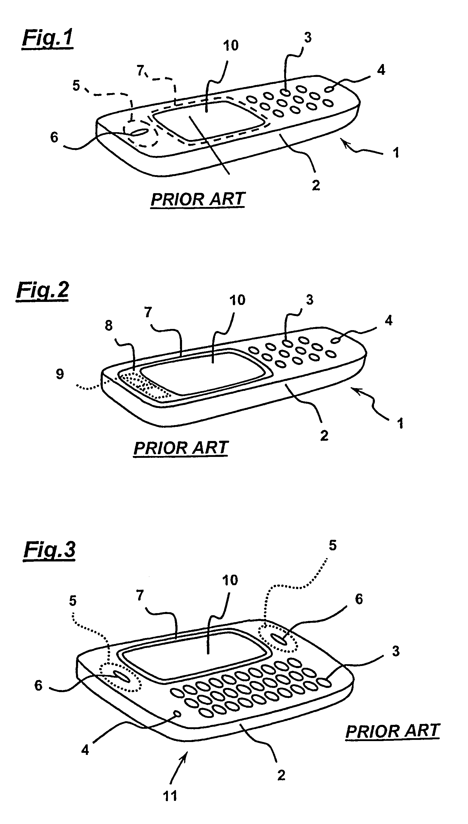
[0062]In FIG. 1 there is shown a prior art mobile telephone handset (1) comprising a housing (2), a keyboard (3), a microphone (4), and a micro speaker (5) and its associated sound radiation aperture (6). There is also a display screen (10) viewable through a protective transparent cover (7). The display screen cover (7) is slightly larger than the viewable area of the screen (10) which is defined by a corresponding aperture in the housing (2).

[0063]In FIG. 2 there is shown a prior art mobile telephone handset (1) where the transparent display screen cover (7) has a marginal region (8) fitted with an electrodynamic exciter (9) which drives the cover in bending wave vibration to radiate sound. The cover thus acts as a resonant panel-form speaker. Such an arrangement is described in International Application WO00 / 02417. The exciter (9) may be a beam type piezo modal actuator, e.g. of the kind described in International Application WO01 / 54450.

[0064]FIG. 3 shows a PDA (11), that is a pe...


PUM


Abstract

From one aspect, the invention is a method of making a bending wave panel loudspeaker, comprising rigidly coupling a lever to a panel edge or marginal portion such that the lever extends at an angle to the plane of the panel, coupling a bending wave exciter to the lever whereby bending wave energy is coupled to the panel to produce an acoustic output when the exciter is fed with a signal and supporting the panel on a suspension positioned outboard of the lever. From another aspect the invention is a bending wave panel-form loudspeaker having a lever rigidly coupled to a marginal portion or edge of the panel, a vibration exciter coupled to the lever to apply bending wave energy to the panel to produce an acoustic output and a panel suspension positioned outboard of the lever. From a further aspect, the invention is a small electronic device, e.g. a mobile telephone or PDA, having a display screen, and a transparent protective cover over the display screen, wherein the transparent protective cover is a loudspeaker as described above.

Description

[0001]This application claims the benefit of U.S. provisional application No. 60 / 534,979, filed Jan. 9, 2004.TECHNICAL FIELD[0002]The invention relates to a method and apparatus for applying force to loudspeaker diaphragms of the bending wave panel-form kind, and more particularly to resonant bending wave loudspeakers e.g. of the kind described in International Application WO97 / 04842 and known as Distributed Mode Loudspeakers.[0003]The invention relates more particularly, but not exclusively, to bending wave acoustic diaphragms applicable to small electronic devices such as mobile telephones, PDAs and the like which have a transparent plastics cover or protector over a display screen section and where it is valuable to combine the protective function of this cover with that of a bending wave loudspeaker.[0004]It is an object of the invention to increase the viewable area of a display screen.BACKGROUND ART[0005]It is known to drive a bending wave loudspeaker panel near its centre by ...

Claims


Application Information

Patent Timeline
IPC IPC(8): H04R25/00H04R7/04
CPCH04R7/045H04R2499/15H04R2440/05H04R2440/01H04R7/00H04R7/04
Inventor AZIMA, HENRYHARRIS, NEIL GEOFFREYMORECROFT, DENISSTARNES, MARKCOLLOMS, MARTINBURTON, PAUL
Owner GOOGLE LLC
Learn More