
Dispensing system for dispensing warm wet wipes

a technology for dispensing systems and wet wipes, which is applied in the direction of lighting and heating equipment, instruments, and domestic cooling equipment, etc., can solve the problems of affecting the overall utility and desirability of baby wet wipes currently on the market, affecting the quality of baby wet wipes, and affecting the overall utility and desirability of the product, so as to facilitate the rupturing of the micro-encapsulated delivery equipmen

Inactive Publication Date: 2010-01-19
KIMBERLY-CLARK WORLDWIDE INC
View PDF48 Cites 9 Cited by
  • Summary
  • Abstract
  • Description
  • Claims
  • Application Information

AI Technical Summary

Benefits of technology

The system effectively provides a warming sensation while preserving the moisture and integrity of the wet wipes, enhancing user comfort and safety by eliminating the need for external heating sources.

Problems solved by technology

In recent studies, it has been shown that baby wet wipes currently on the market are sometimes perceived to be uncomfortably cold upon application to the skin, particularly for newborns.
Though such currently known and available wet wipe warming products typically achieve their primary objective of warming the wet wipe prior to use, they possess certain deficiencies, which can detract from their overall utility and desirability.
Perhaps the biggest deficiency of the current wet wipe warming products and dispensers is their inability to sustain the moisture content of the wet wipes.
More specifically, drying of the wet wipes occurs due to heating of their moisture which accelerates dehydration.
As a result, wet wipes may become dried-out and unusable.
Other complaints by wipe warmer users include discoloration of the wet wipes after heating, which appears to be inevitable because of a reaction of various chemicals in the wipes upon the application of heat.
Wipe warmer users further complain about warmer inconvenience and potential electrical fire hazards, which can result with the use of electrical warming products.

Method used


Image

  • Dispensing system for dispensing warm wet wipes
  • Dispensing system for dispensing warm wet wipes
  • Dispensing system for dispensing warm wet wipes

Examples


example 1

[0167]In this example, samples incorporating various size ranges of anhydrous calcium chloride suspended in mineral oil at 35 wt % were evaluated for their ability to generate heat upon introduction into water.

[0168]The five size ranges of anhydrous calcium chloride evaluated were: (1) less than 149 microns; (2) 149-355 microns; (3) 710-1190 microns; (4) 1190-2000 microns; and (5) 2000-4000 microns. The samples of anhydrous calcium chloride (Dow Chemical, Midland, Mich.) were dispersed in mineral oil (available as Drakeol 7 LT NF from Penreco, Dickinson, Tex.). The as received anhydrous calcium chloride were screened dry using a Gilson Sonic Sieve (Gilson Company, Inc. Columbus, Ohio) to create two sizes, a 1190-2000 micron size and a 2000-4000 micron size. These powders were then suspended at 35 wt % in mineral oil to form a slurry using a cowles mixing blade. To achieve the smaller size distributions, the anhydrous calcium chloride powder required further processing.

[0169]Specific...

example 2

[0172]In this example, samples incorporating various size ranges of anhydrous magnesium chloride suspended in mineral oil at 35 wt % were evaluated for their ability to generate heat upon introduction into water.

[0173]The four size ranges of anhydrous magnesium chloride evaluated were: (1) 1000-1500 microns; (2) 600-1000 microns; (3) 250-600 microns; and (4) less than 250 microns. To produce the samples of anhydrous magnesium chloride in mineral oil, the various size ranges of anhydrous magnesium chloride powder (Magnesium Interface Inc. (Vancouver, B.C., Canada) were suspended at 35 wt % in mineral oil (available as Drakeol 7 LT NF from Penreco, Dickinson, Tex.). To produce the samples having anhydrous magnesium chloride with size ranges of 1000-1500 microns, 600-1000 microns, and 250-600 microns, the as received anhydrous magnesium chloride powder was hand screened into the size ranges desired and the powders collected. These powders were suspended at 35 wt % in mineral oil using ...

example 3

[0176]In this Example, six compositions including a heating agent, matrix material, and various surfactants were produced. The viscosities (at 23° C.) of the compositions were measured using a Brookfield Viscometer to determine which surfactants were preferred for use in the compositions of the present disclosure.

[0177]To produce the compositions, 34.7% (by weight composition) anhydrous magnesium chloride (available from Magnesium Interface Inc., Vancouver, B.C., Canada), 64.3% (by weight composition) mineral oil (available as Drakeol 7 LT NF from Penreco, Dickinson, Tex.), and 1.0% surfactant (by weight composition) were milled together using a vertical attritor mill using one quarter inch, spherical, ceramic media for a total of 90 minutes. The surfactants utilized in the six compositions and their properties are shown in Table 1.

[0178]

TABLE 1CommercialIonicSurfactantSourceActivityAntiterra 207BYK ChemieAnionic(Wesel,Germany)Disperbyk 166BYK ChemieProprietary(Wesel,Germany)Disperb...


PUM


Abstract

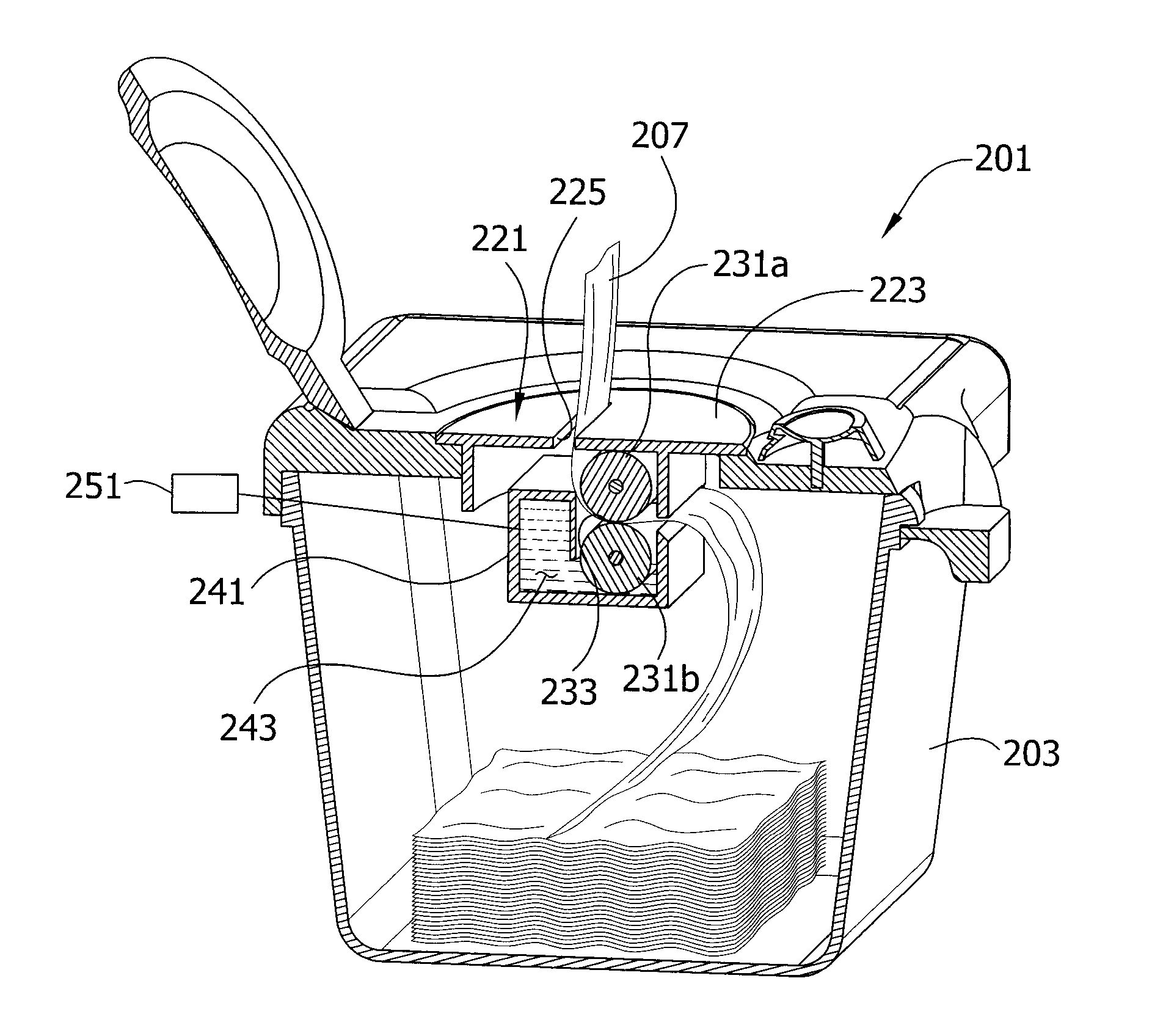
In a dispensing system for dispensing wet wipes, a wet wipe has an aqueous solution and microencapsulated delivery vehicles including a temperature agent, and is disposed in a wet wipe container. A cartridge is held in assembly with the wet wipe container and has an activating device that facilitates rupturing of the microencapsulated delivery vehicles as the wet wipe is removed from the dispensing system to allow contact between the temperature change agent and the aqueous solution of the wet wipe to thereby dispense a warm or cooled wet wipe. In another embodiment, the wet wipe has an aqueous solution and a lotion having the microencapsulated heat delivery vehicles disposed in the cartridge free from contact with the wet wipe. The cartridge also has an applicator that is operable to apply the lotion to the wet wipe as the wet wipe is removed from the wet wipe container.

Description

BACKGROUND OF THE DISCLOSURE[0001]The present disclosure relates generally to dispensing systems for dispensing warm wet wipes or wet wipes capable of warming quickly after being dispensed, and processes for dispensing warm wet wipes or wet wipes capable of warming quickly after being dispensed. The warming sensation on the surface of the wet wipe is caused by the interaction of a heating agent initially contained in a microencapsulated heat delivery vehicle with an aqueous solution contained in the wet wipe.[0002]Wet wipes and related products have been used for some time by consumers for various cleaning and wiping tasks. For example, many parents have utilized wet wipes to clean the skin of infants and toddlers before and after urination and / or defecation. Many types of wet wipes are currently commercially available for this purpose and are known in the art.[0003]Today, many consumers are demanding that personal health care products, such as wet wipes, have the ability to not onl...

Claims


Application Information

Patent Timeline
Patent Type & Authority Patents(United States)
IPC IPC(8): G07F9/10
CPCA47K10/421F28D20/023A47K2010/3286A47K2010/3293A61F7/032Y02E60/145Y02E60/14A47K10/32A47K10/42
Inventor SOSALLA, GERALDSCHMIDT, PAUL R.MILNER, JAMES DELLJOSEPH, WAEL R.MCDONALD, DUANE LYLE
Owner KIMBERLY-CLARK WORLDWIDE INC
Learn More