Combine harvester power management control

a technology of power management control and combine harvester, which is applied in the field of combine harvester, can solve the problems of operator risk exceeding the capacity of a subsystem, reducing available engine power, and requiring a substantial amount of residual power, so as to prevent damage, failure or poor functional performance, and reduce available engine power

Active Publication Date: 2010-01-19
BLUE LEAF I P INC
View PDF16 Cites 54 Cited by
  • Summary
  • Abstract
  • Description
  • Claims
  • Application Information

AI Technical Summary

Benefits of technology

[0012]According to a preferred aspect of the invention, the control utilizes a methodology for limiting available engine power, as a function of engaged subsystems, and the configuration or configurations of the subsystem or subsystems, such that at least a reasonably close approximation of actual power usage can be determined, and the selected maximum available power will closely match possible needed power. Thus, according to the invention, available engine power is reduced with the removal or recognition of disengagement of different subsystem(s) from the total vehicle configuration, and also with the configuration of operational subsystems, at less than their maximum power consumption. The intent is to provide adequate but not excessive horsepower to the configured vehicle to insure functional and / or mechanical performance is not exceeded.
[0013]With current available electronic control systems, utilizing a processor based controller, the presence, operation and load of any subsystem (header, straw chopper, etc) can be sensed. According to the invention, from recognition, speed, or load signals, the engine controller would have a predefined table of engine power, e.g., horsepower (HP), levels of which would increase or decrease from a set point the appropriate maximum available power to operate the employed subsystems. As with current unload systems, when the engine controller receives a signal of unloader engagement, the engine is allowed to increase horsepower to offset additional power requirements of the unload system. Also according to the invention, if the straw chopper (large consumer of net horsepower) were removed or not in use, the engine controller will automatically reduce available engine power by the typical chopper power consumption for the selected crop setting, thus not limiting vehicle function but maintaining the appropriate operational power supply to the employed vehicle subsystems, thereby preventing damage, failure or poor functional performance.
[0014]Thus, according to the invention, the control is not adding power but limiting or reducing power via mechanical or electronic signal for user defined continuous operation cycles providing overload protection for peripheral subsystems of the subject vehicle.
[0018]Stationary chopper knife bank position sensor. Maximum HP is available when knives are fully engaged, as knives are incrementally retracted to reduce chop length, available engine power is controlled so as to be correspondingly reduced.

Problems solved by technology

Residue chopping also requires a substantial amount of power, especially when chopping straw of small grain crops, such as wheat and barley.
Each of these configurations will have its own required power level that will be less than the full amount of power that the engine is able to direct to the subsystems, such that if available maximum power is not properly managed for a given configuration, damage can result.
And, conversely, if insufficient maximum power is available, performance can suffer.
By doing so, however, an operator risks exceeding a subsystem's capacity.
For example, threshing efficiency typically decreases drastically if too much crop is taken in.
Overload will eventually result in excessive wear / and or deformation of the components of the crop processing subsystem.
Elements of the threshing system, such as threshing slats, may bend and threshing concaves may become distorted.
The available amount of power may also exceed the mechanical limitations of the driveline to the threshing drum, thereby shortening the lifetime of components such as drive belts and gearboxes.
However, an observed shortcoming of setting maximum available power as a function of overall operating mode as suggested above in the first patent, and based on header identity alone, such as proposed in U.S. Pat. No. 6,397,571, is that too much available power may be present in instances when less than all crop processing subsystems are engaged.
As noted above, these subsystems often are significant contributors to the total consumed power.
In many cases, however, this can result in substantially overrunning the subsystems' functional capability, resulting in grain loss, etc., or exceeding mechanical limits causing failures.
It is not cost effective to design every system to carry the maximum available power for a plethora of configurations, but rather it would be preferred to limit available power to the subsystem not exceeding its performance limits.
Setting maximum available power based on the identity of engaged or activated subsystems such as by monitoring on / off switches as proposed in U.S. Pat. No. 5,878,557, also suffers from a shortcoming that practically, it will necessitate setting the available power level to accommodate the maximum expected power usage of those subsystems, and doesn't accommodate reduced power needs of different configurations of the subsystems.
Thus, this system falls short of providing a closely tailored level of available power for different subsystem configurations having different power needs.
Setting maximum available power as a function of measured actual usage, as proposed in U.S. Pat. No. 6,073,428, suffers from the shortcoming that it must rely on measurement means that can be unreliable, inaccurate, and / or complex, and can require calibration to ensure accuracy, so as to be of limited practicality.
Also, the actual power usage can vary significantly during operation as a result of temporary or intermittent operating conditions such as passage of slugs of crop material through the crop processing systems, such that the level of available power will be correspondingly varied, reactive to demand, as opposed to in anticipation of demand, which can be problematic.
But, when an abrupt increase in power demand occurs, such as entry of a slug of dense crop material into one or more of the crop processing subsystems, e.g., the threshing system, chopper, or spreader, the additional engine power available may be inadequate.
This inadequate power can cause the engine to bog down or stall, such that other subsystem performance suffers.
Then, if in response the system automatically or the operator manually increases power, after the need for the additional power has passed, the now available power will not closely match actual power needs.

Method used


Image

  • Combine harvester power management control
  • Combine harvester power management control
  • Combine harvester power management control

Examples


Embodiment Construction

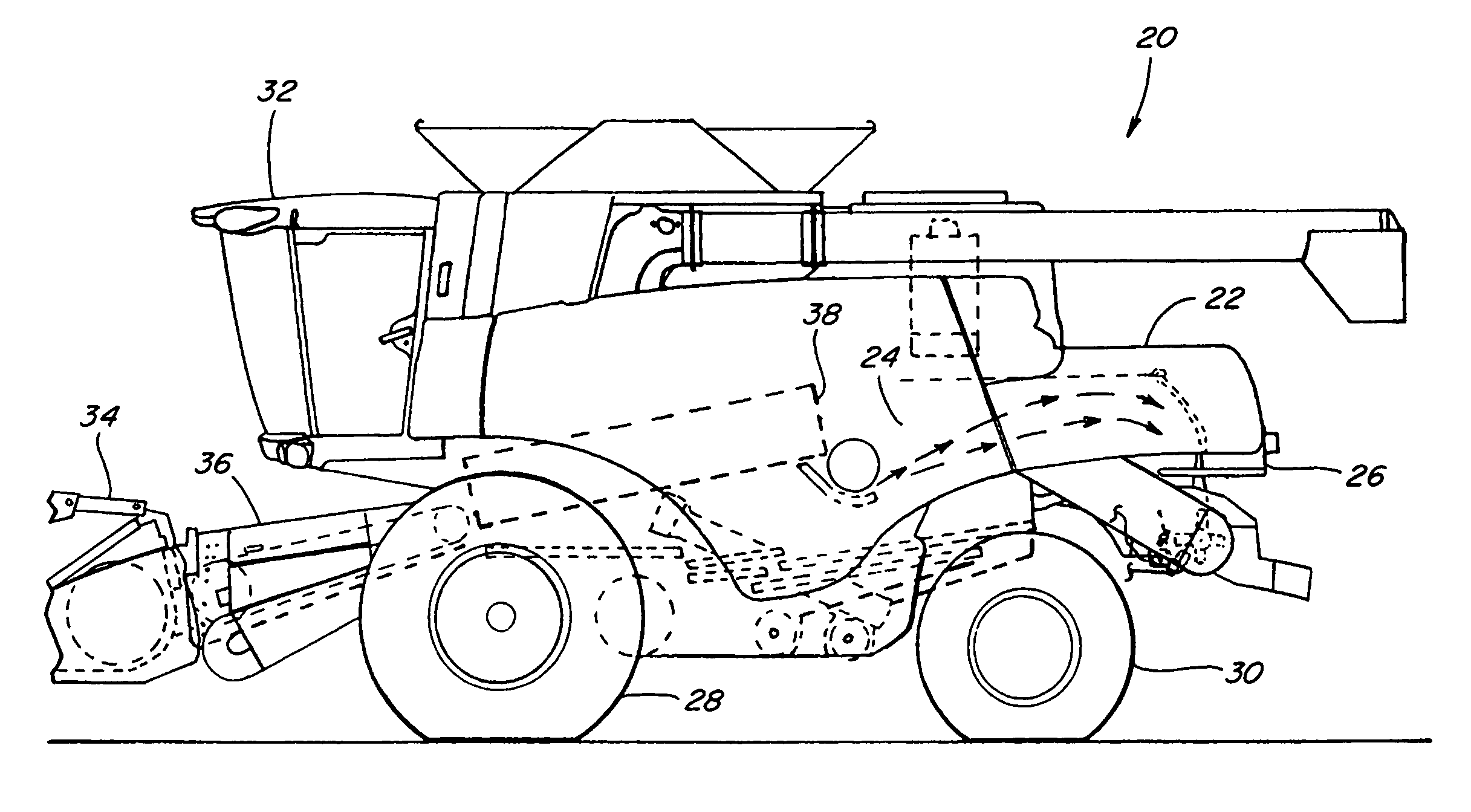
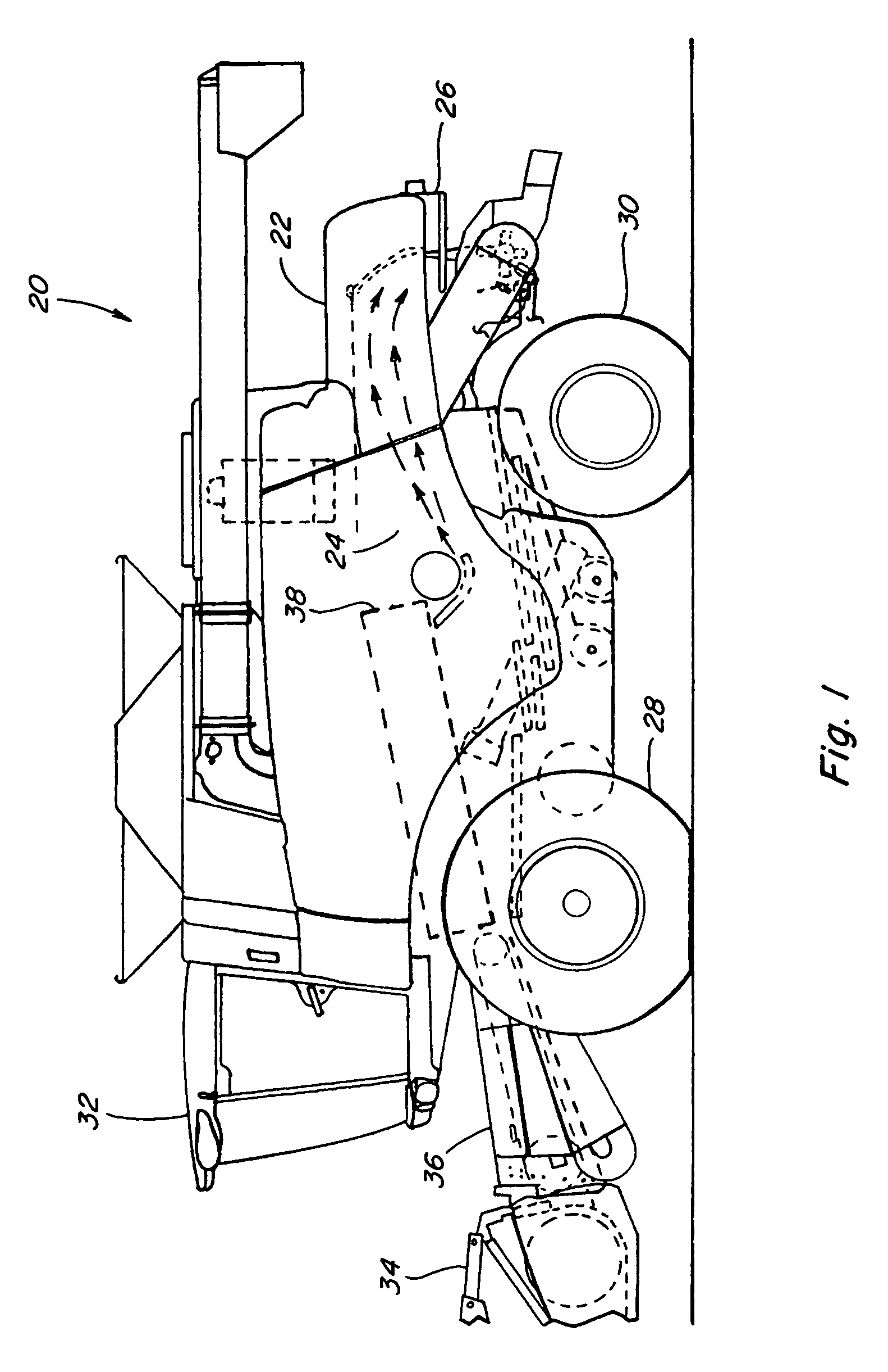
[0039]Referring to the drawings, FIG. 1 shows a self-propelled rotary combine 20 representative of those with which the automatic control system operable for setting a level of maximum engine power according to the invention, can be used. While a conventional rotary combine is shown, it is anticipated that the present invention could be used with any type of combine, such as a conventional combine having a threshing cylinder and separation beaters (not shown) or a hybrid combine having a threshing cylinder and rotors (not shown). However, for ease of explanation, the present invention will be discussed hereinafter in conjunction with a self-propelled rotary combine 20 as illustrated by FIG. 1.

[0040]Combine 20 includes a housing or body 22 defining an internal open area or space 24. The body 22 of the combine 20, which can include a supporting frame 26, is supported on front drive wheels 28 and steerable rear wheels 30. The combine 20 is powered by an engine 126 and controlled from a...


PUM


Abstract

A system and method of controlling maximum available engine power of a combine harvester wherein the engine drives the harvester and additionally powers a threshing mechanism for separating harvested crop into grain and crop residue and at least one further crop processing subsystem that may be selectively configured and disengaged, including a straw chopper engageable for chopping the crop residue and propelling the chopped residue from the harvester, structure configurable for directing the crop residue into the chopper or to bypass the chopper, utilizing a controller for automatically reducing the maximum available engine power as a function of the status of the engagement of the subsystems, particularly the chopper and the configuration of the associated structure.

Description

[0001]This application claims the benefit of U.S. Provisional Application Ser. No. 60 / 904,235, filed Mar. 1, 2007.TECHNICAL FIELD[0002]The present invention relates generally to a combine harvester having an engine for driving the harvester and for additionally powering a threshing mechanism for separating harvested crop into grain and crop residue and at least one further crop processing subsystem that may be selectively configured and disengaged, and more particularly, the invention relates to a system and method for managing maximum engine power responsive to a variety of different subsystem configurations or operating modes having different power needs, such that the available power more closely matches anticipated needs of the threshing mechanism and crop processing subsystems, thus reducing the possibility of overpowering the subsystems.BACKGROUND[0003]The current marketplace for work machines, and particularly agricultural machines such as combine harvesters, is substantially...

Claims


Application Information

Patent Timeline
Patent Type & Authority Patents(United States)
IPC IPC(8): A01F12/40
CPCA01D41/127
Inventor DUQUESNE, FRANKVAN OVERSCHELDE, DANIEL M. G.FARLEY, HERBERT M.
Owner BLUE LEAF I P INC
Why Eureka
Try Eureka